Download

1 / 86
860 likes | 1.01k Vues
Architectures of Digital Information Systems Part 4: Caches, pipelines and superscalar machines. dr.ir. A.C. Verschueren Eindhoven University of Technology Section of Digital Information Systems. The memory speed ‘gap’.

E N D
Architectures ofDigital Information SystemsPart4: Caches, pipelines and superscalar machines dr.ir. A.C. VerschuerenEindhoven University of TechnologySection of Digital Information Systems
The memory speed ‘gap’ • High-performance processors are much too fast for the main memory they are connected to • Processors running at 1000 MegaHerz would like a memory read/write cycle time of 1 nanosecond • Large memories with (relatively) cheap RAM’s have cycle times on the order of 100 nanoseconds 100 times slower, this speed gap continues to grow...
4 words in parallel 4 accesses in parallel read 0..3 4..7 read 0 1 2 3 4 5 6 7 use use 0 1 2 3 4 5 6 7 0 1 2 3 4 5 6 7 1) Wide memory words 2) Multiple memory 'banks' Wide words and memory banking • The gap can be closed IF the processor tolerates a long delay between the start and end of a cycle Complex timing Lots of pins
The big IF in closing the gap • Long memory access delays can be toleratedIF addresses are known in advance • True for sequential instruction reads • NOT true for most of the other read operations • Memory reading MUST become quicker! • Not interested in (timing of) write operations • Data & address to memory, then forget about it...
‘Cache’ is French:‘secret hiding place’ Small-scale virtual memory: the cache • A 'cache' is a small but very fast memory which contains the 'most active' memory words IF a requested memory word is in the cache THEN supply the word from the cache {very fast} ELSE supply the word from main memory {rather slow} and place it in the cache for later references (throwing out not used words when needed) • An ideal cache knows which words will be used soon • A good cache reaches 95% THEN and only 5% ELSE
Keeping the cache hidden • The cache must keep a copy of memory words • Memory mapped I/O ports are problematic • These can spontaneously change their value ! • Have to be made'non-cacheable’ at all times • Shared memory is problematic too • Make it non-cacheable (from all sides), or better • Inform all attached caches of changes (write actions)
Cache writing policies 'write-through’: written data copied into memory • Option: write to cache only if word is already present • The amount of data in the cache can be reduced • Read after non-cached write requires true memory read 'posted write’: writes buffered until the bus is free • Gives priority to reads, allows high speed write bursts • More hardware, delay between CPU and memory write 'late write’: write only to make free space in cache • Reduces the amount of memory write cycles drastically • Complex cache control, especially with shared memory! Pentium
data bus switch data cache memory CPU main (80386) memory cache controller (82385) address address control administration control system bus CPU bus An example of a cache • To reduce the amount of administration memory, a single cache 'line' administrates 8 word blocks
17 10 3 2 32 bitsaddress: 'tag' line word byte word select 'hit' 'word valid' 'word valid' 1024lines 17 bit tags 32 bit data 32 bit data Lineselect 'line valid' word #0 word #7 Intel 82385 'direct mapped’ cache mode • Also known as '1-way set associative’prone to ‘tag clashing’ !
18 9 17 10 3 2 32 bitsaddress: 'tag' line word byte word select hitlogic 'hit' 'hit' 'word valid' 'word valid' 512lines 18bit tags 1024lines 17 bit tags 32 bit data 32 bit data Lineselect LRU bits 'line valid' word #0 word #7 Intel 82385 ’2-way set associative’ mode • ’Least Recently Used' bits indicate which set in each line has been used last (the other is replacement target)
The MESI protocol • Late write and shared memory combine badly • The 'MESI' protocol solves this with four states for each of the cache words (or lines) Modified: cached data differs from the main memory and is only located in this cache Exclusive: cached data is the same as main memory and is only located in this cache Shared: cached data is the same as main memory and also located in one or more other caches Invalid: cache word/line not loaded with memory data
State changes in the MESI protocol • Induced by processor read/write actions and actions of other cache controllers • Caches keep track of other read/write actions • Uses ’bus snooping’:monitoring the address and control buses when they are driven by someone else • During a memory access, other cache controllers indicate if one of them contains the accessed location Needed to decide between the Shared/Exclusive states!
Intel 82496 CPU accesses Pentium • A read hit reads the cache, does not change state • A read miss reads memory, other controllers check if they also contain the address read • A write hit handling depends on the state • If Shared, write is done in main memory too • If Exclusive or Modified, write is only done in cache • A write miss writes to memory, but not the cache Other caches may change their state! Normal MESI:write cache too
read hit write miss read miss & somewhere else Invalid Shared snoop write snoop write snoop read write hit (write to memory) snoop write read miss, only here snoop read (*) readhit Modified Exclusive write hit (setup for late write) read/writehit Intel 82496 state diagram snoop read anysnoop (*): This controller copies localdata to memory immediately
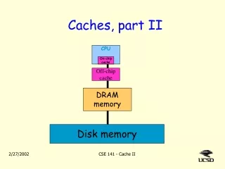
CPU chip mainmemoryhuge& very slow off-chipcachelarge(r)& slow(er) on-chipcachesmall& fast CPU Final remarks on caches (1) • High performance processors rely on caches • Main memory must be accessed in a single clock cycle • At 1 GHz, the cache must be on the CPU chip • But a large & fast cache takes a lot of chip space! Second level cache First level cache
Final remarks on caches (2) • The off-chip cache becomes as slow as main memory was some time ago... • Second level cache placed on the CPU chip too • Examples: power-PC, Crusoe (both > 256 KiloByte!) • The external cache becomes a third-level cache • Data transfer between on-chip caches can be done a complete cache line in parallel: a huge speedup
Speeding it up: which speed ? • It is nice to talk for hours on how to increase the speed of a processor, but... what do we actually want ? • We first have to look at the application side, where speed is more measured in terms of algorithm execution performance thanprocessor performance
Different applications, different speeds • Fixed function (control) applications:the required algorithms must be executed in a given amount of time, expensive and unnecessary to go any faster ! • Transaction processing and databases:the algorithms must be executed at a speed so that the system is not perceived to be 'slow' by human standards • ’Number crunching' and simulations:the algorithms must be executed as fast as possible The last one is used the least !
Number crunching and simulation (1) • The only applications where algorithm processing speed is of major concern • A single operation may take hours or even days! • It may be worthwhile to spend a lot of money to increase processing speed by 'only' 10% • These users are willing to upgrade their computer once a year to follow the latest technology trend...
Number crunching and simulation (2) • 'No holds barred' - all tricks in the book are used • Massively parallel processor systems • Special purpose hardware • Vector processors and 'systolic arrays’('Single Instruction Multiple Data’ machines) • 'Normal' processors speeded up by all kinds of tricks often based upon the type of operations to be performed We will focus on some of these tricks
Algorithm processing speed • The clock speed of a processor doesn't say much • The Rekursiv machine (vCISC) at 10 MHz beatsa TI 'LISP engine' (RISC) at 40 MHz to run LISP • The reason: Rekursiv can ‘Malloc’ in one clock cycle • It is possible to optimise a processor architecture to fit the programming language • which may give tremendous speedups(f.i. LISP, Smalltalk or Java)
The problem with ‘benchmarks’ MeaninglessInformation aboutProcessorSpeed • 'Million Instructions Per Second’is an empty measurement unless scaled to some normalised instruction set and 'mix' • 'Standard' benchmark programs are not representative of real applications their instruction mix is non-standardand results are influenced by the compiler which is used
Reduced Instruction Set Computers • Execute a 'simple' instruction set(load/store philosophy: operations between registers only) • Have fixed length instructions with a few formats(easy to decode but sometimes space inefficient) • Use a large number of general purpose registers(needed for calculating addresses and reduce reads/writes) • Tuned for high-speed instruction execution • But not high speed 'C' execution, as some believe
Complex Instruction Set Computers • Execute a complex instruction setdoing much more in one instruction, difficult to decode • Have variable length instructionsgives higher storage efficiency and shorter programs • Use a moderate number of registers(some of them special purpose) • Tuneable towards high-level language execution • f.i. 'ENTER' and 'LEAVE' instructions in the 80286 • or even operating system support (task switching)
The RISC/CISC boundary fades fast • 'RISC' is sometimes a completely misplaced label • The IBM 'POWER' architecture knows more instructions than an average CISC • RISC speed ('one instruction per clock') can also be reached by modern CISC processors • Which then perform the equivalent of several RISC instructions in that same 'single clock'
The number of instructions per clock 'one instruction per clock' (1 IPC)is hardly ever reached, even for RISC CPU's • Early RISC's reached 0.3 .. 0.5 IPC • it takes a lot of hardware to reach 0.6 .. 0.7 IPCwhen running normal programs ! • Only 'Superscalar' processors can reach(and even exceed) 1 IPC
Standard CISC instruction execution • In the old days, a CISC processor took a lot of clocks to execute a single instruction 1: fetch the (first part of the) instruction 2: decode the (first part of the) instruction 3: fetch more parts of the instruction if needed 4: fetch operands from memory (after address calculations) and/or registers 5: perform ALU operation (may take several cycles) 6: write result(s) to registers and/or memory
A program to execute programs • These old machines interpret the actual program • They ran a lower-level ('microcode') program! • Hardware was expensive, so it was re-used for different purposes during different clock cycles • A single bus to transfer data inside the processor • One ALU for addresses and actual operations
Streamlining the execution on a RISC • Early RISC processors could break instruction execution into four basic steps 1: Fetch instruction (always the same size) 2: Decode instruction and read source operands (s1, s2) 3: Execute the actual operation in the ALU 4: Write result to destination operand (d) • We will denote these four steps with the letters FDEW from now on...
clock data registers s1 s2 d instruction program PC memory + 1 ALU Single clock RISC instruction execution • The basic intruction execution steps can be executed within one clock
setup time to clock clock delays prog. addr. instruction source ops ALU result clock cycle Single clock RISC execution timing • This is a bit slow in terms of clock speed
clock control data registers s1 s2 d unit instruction program PC I memory S1 + 1 ALU D S2 Extra registers for the one clock RISC • The clock speed can be increased by adding extra registers
Timing of RISC with extra registers • The control unit tells all registers when to load 1: Read program memory and store in 'I', PC++ 2: Read source registers and store in 'S1'/'S2’ 3: Perform ALU operation and store result in 'D’ 4: Write 'D' contents into destination register • Less done in each clock cycle: clock speed higher but the number of clocks per instruction goes up and the total instruction execution time increases !
multiplexer s1 clock control data s2 regs unit d instruction program I PC memory S1 + 1 D ALU S2 Reducing hardware costs • The previous solution can be optimised a lot to reduce hardware costs
The ‘reduced hardware costs’ timing • Separate clock cycles for reading operands • The data registers have become single ported(much less hardware than 3-ported) • It is even possible to do PC++ with the ALU • Back at square one:this is how they used to do it in the old days... VERY slow
data registers s1 s2 d program PC I1 I2 I3 memory + 1 S1 D ALU S2 stage 1 Fetch stage 2 stage 3 stage 4 Decode Execute Write Splitting the processor in ‘stages’ • By adding even more registers,we can split the processor in 'stages'
The stages form a ‘pipeline’ • Each stages uses independent hardware • Performs one of the basic instruction execution steps • The stages can all work at the same time • In general on different instructions ! • This way of splitting a processor in stages is called 'pipelining'
clock X X + 1 X + 2 X + 3 stage 1 fetch inst fetch inst fetch inst fetch inst N N+1 N+2 N+3 stage 2 ? read source read source read source N N+1 N+2 stage 3 ? ? ALU op ALU op N N+1 stage 4 ? ? ? write dest N The timing of a pipeline • These stages handle 4 instructions in parallel • At roughly four times the clock speed of the first hardware implementation!
multiply uses 2 extra clocks in ALU r1 := r2 + 3 F D E W r3 := r4 x r5 F D E E E W r6 := r4 - 2 F D E W (must wait for E) r7 := r2 - r5 F D E W (must wait for D) r0 := r5 + 22 F D E (must wait for F) Time ‘stall cycles’ Giving more time to a pipeline stage • A pipeline stage which cannot handle the next instruction in one clock cycle, has to 'stall' the stages in front of it W
The bad thing about pipeline stalls • Stalls force 'no operation' cycles on the expensive hardware of the previous stages • The following instructions finish later than absolutely necessary Pipeline stalls should be avoided whenever possible !
r2+3 22+3 25 r1 := 25 initial values: r1 = 11 25 r1 := r2 + 3 D E W r2 = 22 9 r4 := r3 – r1 F D E r3 = 34 r3-r1 34–11 23 r4 := 23 wrong value! '25' not written yet... Another pipeline problem: ‘dependencies’ • In the standard pipeline, instructions which depend upon eachother's results give problems F W
r2+3 22+3 25 r1 := 25 25 r1 := r2 + 3 D E W 9 r4 := r3 - r1 F D D r3-r1 34-11 34-25 9 r4 := 9 D source = E destination D source = W destination Solving the dependency problem • Compare D, E and W stage operands,stall the pipeline if a match is found F D E W
data registers s1 s2 d control program PC I1 I2 I3 memory result forwarding ‘path’ + 1 s1 S1 ALU D s2 multiplexers S2 stage 1 stage 2 stage 3 stage 4 Fetch Decode Execute Write Result forwarding to solve dependencies { source operand control and multiplexer specification: }IF I3.dest = I2.source1 THEN s1 := D ELSE s1 := S1;IF I3.dest = I2.source2 THEN s2 := D ELSE s2 := S2;
memory pipeline hardware r1 := r2 + 3 F D E W 2 write stages r3 := [r4] F D M M M W r6 := r4 - 2 F D E W forwarding ! r7 := r2 - r5 F D E W r0 := r3 + 22 F D E write orderreversed ! Parallel pipelines to speed things up • No need to wait for the completion of slow operations, if handled by separate hardware W
The ‘order of completion’ • In this example, we have 'out-of-order completion' r6 is written before r3, the instruction ordering suggests r3 before r6 ! • The normal case is called 'in-order completion' Shorthand: ‘OOO’
time source dest order write/read or source dest 'true data dependency' source dest source dest read/write dependency source dest source dest or 'antidependency' Dependencies with OOO completion reading 2nd source must wait for 1st destination write, otherwise wrong source value in 2nd instruction write/write dependency writing 2nd destination must be done after writing 1st destination, otherwise leaves wrong result in destination at end writing 2nd destination must be done after reading first source value, otherwise wrong source value in 1st instruction
‘Scoreboarding’ instead of forwarding • Result forwarding helps in a simple pipeline • It becomes rather complex in a multiple pipeline with out-of-order completion • One of the earlier DEC Alpha processors used more than 40 result forwarding paths • A 'register scoreboard' can be used to make sure that dependency relations are kept in order
Operation of a register scoreboard • All registers have a 'scoreboard' bit, initially reset • Instructions wait in the Decode stage until all their source and destination scoreboard bits are reset (to zero) • Instructions which exit the Decode stage set the scoreboard bit in their destination register(s) • A scoreboard bit is reset during the writing of a destination register in any Writeback stage
Scoreboard performance • A simple scoreboard is very conservative in it's stalling decisions • It stalls the pipeline for true data dependencies But removes all forwarding paths in return ! • Write-write and antidependencies are stalled much longer than absolutely necessary • They should be stalled in the Writeback stage,not the Decode stage !
The real reason for some dependencies • Write-write and antidependencies exist because a register is re-used to hold another value ! • If we use a different destination register for the each write action, these dependencies vanish • This requires changing the program,which is not always possible • The amount of available registers may not be enoughevery result a different register ?