Download
1 / 21
210 likes | 370 Vues
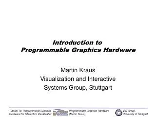
Architectures of Digital Information Systems Part 2: Programmable I/O and Multiprocessors. dr.ir. A.C. Verschueren Eindhoven University of Technology Section of Digital Information Systems. Programmable input/output controllers.

E N D
Architectures ofDigital Information SystemsPart 2: Programmable I/O and Multiprocessors dr.ir. A.C. VerschuerenEindhoven University of TechnologySection of Digital Information Systems
Programmable input/output controllers • Many I/O control tasks can be done in software, using simple parallel ports and timers • Keyboard scanning and encoding • Simple motor control • Pulse counting for position encoding • Other non-standard low speed (but time-critical) tasks • Don’t use main processor for this ‘simple’ stuff ! • Use programmable I/O controllers here:modified single-chip microcomputers
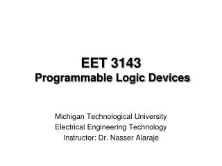
inputs ! 8042 8048 CPU 2KB program 128B data 8 bit parr. I/O data read write master CPU interface address int chip select int 8 bit parr. I/O (not) input full output full DMA req. 8 bits timer DMA ack. interruptrequests Original 8048: external data bus interface and I/O port The Intel 8042 ‘slave processor’
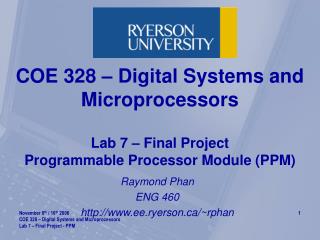
status register input full pin internal interrupt set input full res output full pin res output full set externaldata bus flag 0 'clear/complement/jump f0' s/r flag 1 'clear/complement/jump f1' read status read data load data output register 'out dbb,a' copy ofaddressinput internal data bus 'in a,dbb' data input register load writedata/cmmd The 8042 'master CPU interface' • Flag 0 (and 4 other status reg. bits) are ‘user defined’
The Z8090 Universal Peripheral Controller • Based upon the Zilog Z8 microcomputer • 8 bits CPU, 2 KB program ROM, 256 byte data RAM • Memory mapped I/O includes timers and parr. ports • Master CPU interface differs a lot from 8042 • Master reads/writes 16 byte ‘window’ in data RAMwindow location controlled by Z8090 program • Simple form of DMA to/from data RAMstart and end locations controlled by Z8090 program • Z8090 interrupts master by setting output bit • Master interrupts Z8090 by dummy write action
Co-processors: divide and conquer • A ’co-processor' is hardware which takes over (software) functions from the main CPU This increases the speed of the system as a whole • The CPU has fewer functions to perform • Co-processors can use customised (fast) hardwareinstead of standard hardware running software • Co-processors should not bother the CPU • Use DMA to transfer data, commands and results • Use interrupts to signal important things onlyinterrupts may run in both directions !
’Closely coupled' co-processors • Keep track of instructions executed by main CPU • Are actually controlled by these instructions • Some instructions are treated as 'no-operation' by main CPU • These trigger the co-processor to start a specific operation • Data transfer is done with DMA • The address may be provided by main CPU using a 'dummy' read cycle during execution of the 'no-operation' instruction • Result codes transferred with DMA or special I/O ports • Synchronisation is absent or uses special hardware Used to extend the main CPU instruction set (f.i. floating point)
’Loosely coupled' co-processors • Have no connection with main CPU instructions • May even execute their own programs ! • Commanded by explicit I/O actions from the CPU or command blocks in memory (with an ‘attention’ signal) • Returns results through memory or explicit I/O actions after interrupting the main CPU Used to off-load complete I/O related tasks from the main CPU(for instance the device drivers in an O.S.) Also used to speed complex data processing tasks if theco-processor contains better hardware than the CPU
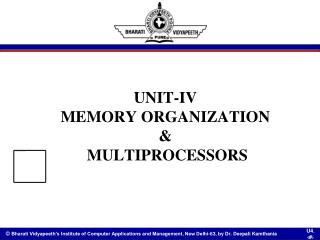
mainprocessor DMAco-processor I/O hardware mainmemory DMAmemory DMA co-processor = programmable I/O • Handle I/O tasks including high speed transfer of data blocks (8042 ‘DMA’ is low speed) • Run their own programs (stored in DMA memory), controlled by 'messages' in main memory
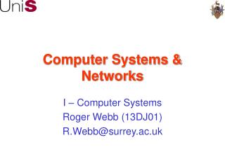
read read write (2-ported) write CPU I/O device addr addr memory data data Shared memory • Direct Memory Access allows both the CPU and I/O devices access to the same main memory • The fastest solution: multi-ported shared memory • CPU and I/O memory accesses do not interfere • Real 2-port memory is very expensive,3 ports and up is not available!
read read write write CPU I/O device addr addr memory wait data data wait arbiter fast(er) memory Shared memory with an arbiter • Multi ported memory may be simulated with an ‘arbiter’ and a higher speed (normal) memory True simultaneous access is impossible! May haveto wait ! Fast memory is expensive !
read read write write sharedmemory sharedmemory I/O device I/O device addr addr data data read select select write CPU addressdecoder addr data select privatememory Combine shared and private memory • Communication confined to a small memory area • CPU works mostly in private memory:using an arbiter does not degrade performance! Simple to have more devices
input/outputmodule I/O proc.+ memory+ I/O ports globalmemorymodule main proc.+ memory ? ! arbiter arbiter ? ! system bus Modular systems • Access to the system bus and shared memories requires arbitration ( = ‘data traffic control’)
I/O proc.+ memory+ I/O ports globalmemorymodule main proc.+ memory 2 1 2 3 Localmemory Localmemory 1 arbiter Sharedlocalmemory Sharedlocalmemory arbiter 2 2 3 3 Globalmemory Globalmemory Mainprocessor I/Oprocessor Memory mapping • Mapping done by address decoding hardware • Which can place memories at different addresses ! • Shared local memories require complex arbiters
‘Standard’ system buses • Standardisation needed for ‘plug and play’ • A lot of them exist (Multibus, VME, EISA....) • Multibus designed by Intel for 80x86 series • VME busdesigned by Motorola for 680x0 series • They compete for the most complex protocols • Bus signals optimised for one processor (series) • Using an Intel processor on a VME bus is not simple
Special purpose co-processors (1) • Relatively simple co-processors with a specialdata path can beat complex standard processors ! • Co-processors for standard algorithms exist Data encryption and decryptionDES and RSA devices are available.Separate devices are preferred because of security reasons ! Data compression and expansionImage (CCITT FAX, JPEG, MPEG)and data file (LZW = ‘ZIP’) (de-)compression devices exist
Special purpose co-processors (2) • Parametrisation is possible with writable ‘constants’ and programmable sequencing logic Fast Fourier Transform devices have programmable address generators and multiplication ‘constants’ (In‑)Finite Impulse Response filters are parametrised in the same way to generate different characteristics 2-D graphics image filter devices are more of the same • Used for noise reduction, smoothing • Edge detection, sharpening, contrast enhancement • Removing distortions and blurr (very complex!)
l å = · out in C - ( ) n n i i = 0 i Finite Impulse Response filter Digital Signal Processing • Lots of Digital Signal Processors (DSP's) have been designed for digital filtering operations • One output requires l adds and (l + 1) multiplications • The last l input values must be remembered and an array of (l + 1) constants must be available somewhere DSP = multiply-add datapath + >1 memory + loop addressing
Digital Signal Processors • Support standard CPU operations:more general purpose than FIR/IIR filter devices ! • They can take decisions based upon the filtered values and switch between different filter characteristics Needed for, for instance, telephone line modems • They can be programmed for 'strange' input value addressing schemes Like used in two-dimensional image filtering
High performance DSP’s: parallel • Multiple on-chip memories with parallel access using independent data and address buses • Multiple I/O interfaces use DMA to read/write the memories in parallel to calculations • Programmable address generators running in parallel to actual multiply/add datapath Actual calculations use floating point for a wider'dynamic range' and lower digital output noise
The ultimate in DSP’s: real-time video • Need on the order of 1 billion operations/second for 3-D picture generation or video filtering Intel’s Multi-Media eXtension (MMX):8 identical byte operations with one instruction Texas Instrument’s 32080:5 processors (w. ‘MMX’) and 25 memories on one chip Philips’ TriMedia:5 ‘MMX’-like instructions in one super-instruction