EET 3143 Programmable Logic Devices
This course provides students with foundational knowledge and hands-on experience in using Hardware Description Language (HDL) for modeling digital systems. With a focus on FPGA technology, students will explore its significance in logic design and learn the complete FPGA design flow using Altera's Quartus II software. Participants will engage in collaborative projects, gain experience in timing analysis, and create SDC files for FPGA design constraints. By the end of the course, students will understand how to synthesize, map, and route designs on an Altera DE2 FPGA evaluation board.

EET 3143 Programmable Logic Devices
E N D
Presentation Transcript
EET 3143 Programmable Logic Devices Michigan Technological University Electrical Engineering Technology Instructor: Dr. Nasser Alaraje
Contact Information • Name: Abdulnasser (Nasser) Alaraje • Office: 417 EERC Building • Phone (O): 487-1661 • Email: alaraje@mtu.edu • Office Hours: MWF 10:00 am – 12:00 pm (or by appointment)
Practical Course • Course Objectives: • Upon Successful completion of this course, students should: • Learn how to use HDL for modeling basic building blocks of digital system • Learn FPGA technology and the impact of using FPGA in logic design • Learn FPGA design flow using Altera’s Quartus® II development software • Gain FPGA design experience by synthesizing, mapping, and placing and routing a given design on Altera’s DE2 FPGA evaluation board • Work in groups of two or three and thereby learn how to cooperate in teams • Gain a basic understanding of timing analysis • Learn how to build SDC files for constraining FPGA designs • Learn how to verify timing on simple design using the TimeQuest analyzer
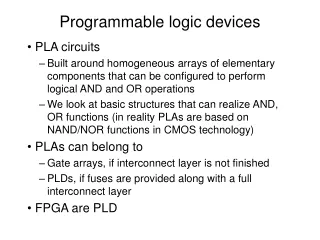
Why FPGA? • Respond to the Market needs of Skilled FPGA Engineers • FPGA-based re-programmable logic design became more attractive as a design medium during the last decade • only 19.5 % of 4-year and 16.5 % of 2-year electrical and computer engineering technology programs at US academic institutions currently have a curriculum component in hardware description language and programmable logic design • Curriculum has not yet “caught up” to industry needs. industry must be driving the curriculum development.
What projects are FPGAs good for • Aerospace & DefenseRadiation-tolerant FPGAs along with intellectual property for image processing, waveform generation, and partial reconfiguration for SDRs. • AutomotiveAutomotive silicon and IP solutions for gateway and driver assistance systems, comfort, convenience, and in-vehicle infotainment. • BroadcastSolutions enabling a vast array of broadcast chain tasks as video and audio finds its way from the studio to production and transmission and then to the consumer. • ConsumerCost-effective solutions enabling next generation, full-featured consumer applications, such as converged handsets, digital flat panel displays, information appliances, home networking, and residential set top boxes. • Industrial/Scientific/MedicalIndustry-compliant solutions addressing market-specific needs and challenges in industrial automation, motor control, and high-end medical imaging. • Storage & ServerData processing solutions for Network Attached Storage (NAS), Storage Area Network (SAN), servers, storage appliances, and more. • Wireless CommunicationsRF, base band, connectivity, transport and networking solutions for wireless equipment, addressing standards such as WCDMA, HSDPA, WiMAX and others. • Wired CommunicationsEnd-to-end solutions for the Reprogrammable Networking Linecard Packet Processing, Framer/MAC, serial backplanes, and more
Who uses them www.fpgajobs.com
Why are they important They have the ability to revolutionize the way that prototyping is done. Allows companies to get to market quicker and stay in market longer.
Xilinx Largest manufacturer of HW Develop hardware and software Embedded PowerPC University Program
Altera Second largest manufacturer Develop HW and SW University Program
Which is best? • It depends • Time • Existing resources • Money • Level of effort • Preference
Hardware/Software? • Software: Quartus Software • Hardware: DE2 FPGA board
Welcome to the Quartus II Software! Turn on or off in Tools Options
Entity • Describes all inputs and outputs • Every VHDL design must has at least one entity • Requires the use of Identifiers for naming the entity itself as well as the inputs and outputs • Entity is a keyword and is reserved in VHDL for this purpose entity <entity identifier> is port (signal identifier); end entity <entity identifier> ENTITY Or2 IS PORT (x: IN std_logic; y: IN std_logic; F: OUT std_logic); END Or2;
Architecture • Architecture declaration is where the operation of the logic function is specified • For each entity there must be a corresponding architecture • Each architecture must be associated by name with an entity architecture < architecture name> of <entity name> is begin The description of the logic function goes here end architecture <architecture name > ARCHITECTURE Or2_beh OF Or2 IS BEGIN PROCESS(x, y) BEGIN F <= x OR y; END PROCESS; END Or2_beh;
VHDL Processes • A process is executed in sequence • Sensitivity list is a list of signals to which the process is sensitive and is optional Name: process (sensitivity list) Declarations Begin Sequential statements End process; PROCESS(x, y) BEGIN F <= x OR y; END PROCESS;
VHDL Components • Predefined logic • Place in a VHDL library and use repeatedly • Any logic function can become a component and used in large programs COMPONENT And2 IS PORT (x: IN std_logic; y: IN std_logic; F: OUT std_logic); END COMPONENT; component name_of_component is port (port definition); end component name_of_component;
Conditional Statements • if-then • if-then-else • elsif • case
If statement • Causes a decision to be made • When the if statement is true, the code following the if statement is executed • When the if statement is false, the code following the if statement until the end if is skipped if conditional statement then VHDL statements end if
If-Then-Else statement • else is an alternative path for the if statement if conditional statement then VHDL statements else VHDL statements end if
Elsif statement • Use to allow multiple alternative paths if conditional statement then VHDL statements elsif conditional statement then VHDL statements elsif conditional statement then VHDL statements end if
Case statement example case expression is when choice => VHDL statement; when choice => VHDL statement; when others => VHDL statements; end case;
Processes in VHDL • Processes Describe Sequential Behavior • Processes in VHDL Are Very Powerful Statements • Allow to define an arbitrary behavior that may be difficult to represent by a real circuit • Not every process can be synthesized • Use Processes with Caution in the Code to Be Synthesized • Use Processes Freely in Testbenches
Logic Operators • Logic operators • Logic operators precedence and or nand nor xor not xnor only in VHDL-93 Highest not and or nand nor xor xnor Lowest
Logic Operators - example Order of evaluation Associative logical operator and, or, xor, xnor are associative. f <= a and b and c; allowed nand or nor is not associative. g <= a nand b nand c; invalid G <= not (a and b and c) ; valid • Need to describe XOR using and, or, not • C = a andnot b ornot a and b • Will be interpreted as: • C = ((a and (not b)) or (not a) and b • C = (ab’+a’)b not correct • Need to use parentheses as follows • C = (a and not b) or (not a and b)
Loops • A loop repeatedly executes the sequential statements contained within the loop structure • for loop • Entry point • Iteration • terminal test for identifier in starting value to stopping value loop VHDL statements end loop
While loop • A for loop stops after a fix number of iterations • A while loop continues to loop until a condition is met • Structure • Entry point • Terminal test • Exit point while Boolean expression loop VHDL statements end loop
Data Types • bit • bit_vector • integer • natural • positive • Boolean • All are keywords • Data types define the type of data and the set of values that can be assigned to.
Integer Data Type • Can contain positive and negative whole numbers • entity declaration sets a range • In the example the output will require 4 pins for the integer entity integer_1 is port( A, B: in bit; Z:out integer range 0 to 15); end entity integer_1
Natural data sub type • A subtype of integer data • Holds whole numbers greater than or equal to zero • In an application limit the range so you limit the number of pins assigned entity natural_1 is port( A: in natural range 0 to 16; X: out natural range 0 to 31); end entity natural_1;
Positive data sub type • A subtype of integer data • Restricts integers to the range from 1 to the specified range limit. entity positive_1 is port( A, B: in bit; Z: out positive range 1 to 31); end entity positive_1;
Boolean Data Type • Has two possible values true and false • In the example below two variables are declared on as true and the other is false variable v1: boolean := false; variable v2: boolean := true:
User-defined enumeration types - Examples type state is (S0, S1); type alu_function is (disable, pass, add, subtract, multiply, divide); type octal_digit is (‘0’, ‘1’, ‘2’, ‘3’, ‘4’, ‘5’, ‘6’, ‘7’);
Functions and Procedures • Types of subprograms in VHDL • Allow for modularization and code reuse • process can also be used as a subprogram, think of a subprogram as a process that is located outside of the architecture of a program. • A function is a subprogram that operates on a set of inputs and returns an output • A procedure is a subroutine that operates on an argument list and passes values back through the argument list • function and procedure will require a call
Function syntax FUNCTION function_name (<parameter_list>) RETURN data_type IS [declarations] BEGIN (function statements) Return value; END function_name;
Function example function and_gate (X, Y: in std_logic) return std_logic is begin return X and Y; end and_gate; To call a function : The output of a function can be assigned to an output port (same data type). Information can also be passed into the function by value. AND1: x<=and_gate (A,B); AND2: x<=and_gate(‘1’, B);
Procedure syntax PROCEDURE procedure_name (<parameter_list>) IS [declarations] BEGIN (procedure statements) END procedure_name; Procedure: similar to a function; however, the arguments in a procedure can include both inputs and outputs (function has inputs only).
Procedure example procedure or_gate(X, Y : in std_logic; Z: out std_logic) is begin Z <= X or Y; end or_gate; To call a procedure: Inputs and outputs are used to pass data in and out a VHDL procedure (same data type). B1: or_gate (A=>X, B=>Y, Z =>V1);
Libraries, Packages and Package Bodies • They hold commonly-used elements and allows them to be stored and used over and over again without having to re-write them. • Components, Procedures and functions are in packages • Packages can be user defined or vendor supplied • Libraries are used to hold packages
Libraries • Two types • Standard libraries (like IEEE standard library) • User defined (holds user-defined packages) • IEEE Standard Library Keyword library: make the packages in the IEEE library visible to the VHDL code. Keyword use: tells the VHDL code what is to be used from the IEEE library. You can specify a specific feature(s) from the package or you can use the keyword all to make them all available. VHDL library coding library ieee; use ieee.std_logic_1164.all; use ieee.std_logic_1164.std_logic;
Packages • Used to hold reusable code • Components • Functions • procedures Package declaration package user_defined_name is package declarations end package user_defined_name;
Package Body • Package body is where items listed in the declaration are defined. Package body syntax package body user_define_name is package body definitions End package body user_defined_name;
Package containing a function (1) LIBRARY IEEE; USE IEEE.std_logic_1164.all; PACKAGE specialFunctions IS FUNCTIONAndGate( A,B: in std_logic) RETURNstd_logic; END specialFunctions; PACKAGE BODY specialFunctions IS FUNCTIONAndGate( A,B: in std_logic) RETURNstd_logic is BEGIN return A AND B; END AndGate; END specialFunctions;
Package containing a function (2) • The package is saved as specialFunctions in the library name work, which is the default library. • Once the package is compiled. It can be used by other VHDL programs. • Example: LIBRARY IEEE; USE IEEE.std_logic_1164.all; USE work.specialFunctions.all; Entity ExamplePackage is Port (A, B: in std_logic; X: out std_logic); End Entity ExamplePackage; Architecture MyGate of ExamplePackage is Begin Process (A,B) Begin A1: X<= AndGate(A,B); End process; End architecture MyGate;
FPGA • Introduced by Xilinx in mid 1980 for implementing digital logic F ield P rogrammable G ate A rray • FPGA Can be visualized as a set of programmable logic blocks embedded in programmable interconnect • Interconnect architecture provides the connectivity between logic blocks • Programming Technology determines the method of storing configuration
FPGA Re-programmable Logic Applications • When FPGA first introduced, it was considered as another form of gate array • SRAM-FPGA in-circuit reprogrammability feature provides a more than just a standard gate array • FPGAs have gained rapid acceptance and growth over the past decade because they can be applied to a very wide range of applications • random logic • Custom computing machine • device controllers • communication encoding and filtering • programmable logic becomes the dominant form of digital logic design and implementation
FPGA design flow • Design Flow is the step-by-step methodology to go through the process of FPGA design • The design flow can be divided into 6 basic steps Design Entry Functional Verification and Simulation FPGA Synthesis FPGA Place & Route Circuit Analysis (Timing, Power …) Programming FPGA devices
Description of Design steps • Design Entry – describes the design that has to be implemented onto FPGA • Functional Verification and Simulation – checks logical correctness of design • FPGA synthesis – converts design entry into actual gates/blocks needed • FPGA Place & Route – selects the optimal position and minimizes length of interconnections on device • Time Analysis – determines the speed of the circuit which has been completely placed and routed • Programming to FPGA – downloads bitstream codes onto FPGA devices
FPGA Design Flow Lets put these design steps in order design entry (VHDL) FPGA Synthesis FPGA Place and Route Download to FPGA FUNCTIONAL VERIFICATION & SIMULATION CIRCUIT ANALYSIS (Timing)
FPGA Design Flow Analysis Path Implementation Path FUNCTIONAL VERIFICATION & SIMULATION design entry (VHDL) CIRCUIT ANALYSIS (Timing) FPGA Synthesis FPGA Place and Route Download to FPGA