Information Transmission
Information Transmission. Course: CIS 3003 Fundamental of Information Technology. This ppt file covers material in Chapter 8 – 10. Objective. How binary streams are physically generated and transmitted with modulation.

Information Transmission
E N D
Presentation Transcript
Information Transmission Course: CIS 3003 Fundamental of Information Technology
Objective • How binary streams are physically generated and transmitted with modulation. • Transmission concept including attenuation, bandwidth, channel capacity, and multiplexing • Properties of various transmission media. • Sources of transmission errors. Error detection and correction techniques.
Transmission and Electron • Metallic conductor material has loose electron • Copper is a metallic conductors.
Ohm’s Law • When a voltage/potential difference from an electrical source, such as a battery, is introduced between the two ends of a conductor, the electrons are stimulated to move within the metal from one atom to another • The relationship between voltage (V), current (I), and resistance (R) is defined by Ohm’s Law: V = IR
Transmission over conductors Analog Binary
Transmission rate of M-ary signaling • Transmission rate of a m-ary signaling D: data rate, R: signals per sec. Calculate the data rate for a communication system using 8-ary signaling at rate of 1000 signals per second.
Transmission over air/vacuum • Electromagnetic (EM) energy • EM waves include radio waves, light waves (infrared, visible, ultraviolet), x-ray, gamma rays. Only radio waves and light wave used in communication • Modulation: varying wave properties to carry information.
Transmission over air/vacuum • Electromagnetic (EM) energy • EM waves include radio waves, light waves (infrared, visible, ultraviolet), x-ray, gamma rays. Only radio waves and light wave used in communication.
EM Wave Characteristics • EM wave is sinusoidal wave • Described by frequency, wavelength (in meters). • λ=c/f where λ is wavelength, c speed of light, and f is frequency.
Wavelength of a wave Calculate the wavelength of a radio wave with 2.5 GHz frequency travelling thru a vacuum.
Modulation • Modulation: carry information through changing the properties of a wave. • Amplitude, phase, frequency. • Demodulation: extract information from a modulated wave.
Phase Modulation • Same frequency as carrier wave. • Shift in phase from carrier wave. • May appear similar to frequency modulation but is not interchangeable; use phase demodulator to interpret a frequency modulated signal creates data error.
Exam 1 • Held next Wednesday 9/28/2011 in class. • Material in Chapters 1 – 5. • No calculator nor computer. Closed books and notes. • True/False, Multiple Choice, Computation problems. • A problem can involve material from multiple chapters. • http://www.cs.ucf.edu/~aho/cis3003/Exam1Review.ppt
Multiplexing • Single line transmits multiple information carrying signals. Single copper carries 24 separate voice streams. • TDM, FDM, Statistical multiplexing, wavelength division multiplexing. • MUX and DEMUX
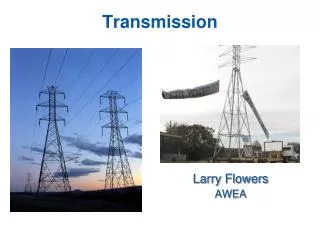
Attenuation • Signals weaken as it travels through medium. • Repeaters amplify signal.
Error in Data Transmission • Error can be caused by attenuation, interference, thermal noise, etc. • Erroneous data can either be resent by the sender or corrected by the receiver.
Parity bit • Parity bit is added to data for error detection. • Even parity: number of 1’s in the data and parity bit is an even number. • Odd parity: number of 1’s in the data and parity bit is an odd number. Data: 1000111 Even parity: 10001110 ---- there are 4 1’s Odd parity: 10001111 --- there are 5 1’s
Single Parity Checking Odd parity check: Transmitted Received 10001111 10000111 There are 5 1’s There are 4 1’s; error Receiver detects error but cannot tell where is the error; the data needs to be resent.
Limitation in Single Parity Checking Odd parity check: Transmitted Received 10001111 11000111 There are 5 1’s There are 5 1’s; Receiver does not detect the error and assume the data is received correctly.
Rectangular Coding • Given two 7-bit data: 1100000 1000101 • Represent the data in a block form • Add parity bit to each data or row of the block • Add a parity bit to each column • Transmitted: 11000000 10001011 01001011
Correction w/ Rectangular Coding Transmitted with even parity coding Received: Receiver can locate and correct error.
Data Transmission with Light • Visible light over fiber optical cable used for computer network communication. • Infrared used by TV remote controls to communicated with TV.
Fiber Optic Cable Refractive index: Speed of light thru vacuum Speed of light thru a medium
Critical Angle • Light travels inside Medium 1 • Light hits at an angle greater than critical angle reflects. • Total internal reflection. • Critical angle depends on the refractive indices of both mediums. • Medium 1 has a higher RI than Medium 2 to keep light trapped in Medium 1
Reflection • Allow fiber optic cable to be bent to a certain degree and routed along structure as needed.
Types of Fiber Optic Cables Single mode • single frequency light such as laser. • Core: 8 –10 µm. Cladding: 125 µm. • 14 Tbit/s in a single 160 km (100 miles) line • Transcontinental network. • Uses laser as light source. Multimode • Core: 50-100’s µm. • 10 Mbit/s to 10 Gbit/s over link lengths of up to 600 meters • Used as backbone network in building • Uses low cost LED as light source.
Fiber-optic Communication • Light emitting diodes (LED)/laser as transducer. • Lowest attenuation at 1.3 and 1.55 µm. • Coupler connects light source and detector with fiber cable. • Repeaters strength signal.
Wavelength Division Multiplexing (WDM) • Two or more light source, each emits a different wavelength. • 10 (coarse) or 100 (dense) channels in one fiber. Mostly used with single mode cable.
Compare Optic to Copper • Higher transmission rate. • Lower attenuation • Immune to. electromagnetic interference. • Harder to eavesdrop. • Harder to splicing (joining two cables). • Light weight. • Low power consumption. • Harder to install – fiber optic is delicate and can be damaged by pulling and twisting.
Applications of Fiber Optics • Internet backbone; Transcontinental connections. http://image.guardian.co.uk/sys-images/Technology/Pix/pictures/2008/02/01/SeaCableHi.jpg • Research on replace wire with fiber optic on chips to overcome noise and attenuation. • Fiber to connect ISP network to consumers. • Fiber optic provides lights and transmit information in endoscope.