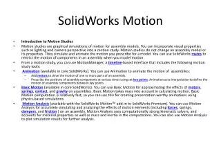

SolidWorks Sweep Feature Guide for Creating Advanced 3D Models
E N D
Presentation Transcript
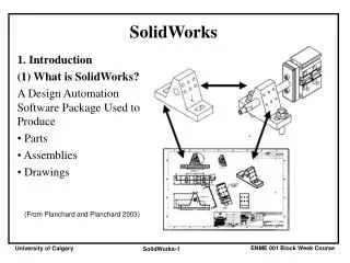
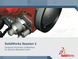
SolidWorks Session 5 Ferdowsi University of Mashhad Dr. Behnam Moetakef Imani
Sweep • Sweep creates a base, boss, cut, or surface by moving a profile (section) along a path, according to these rules: • The profile must be closed for a base or boss sweep feature; the profile may be open or closed for a surface sweep feature. • The path may be open or closed. • The path may be a set of sketched curves contained in one sketch, a curve, or a set of model edges. • The start point of the path must lie on the plane of the profile. • Neither the section, the path,nor the resulting solid can be self-intersecting. • The guide curve must be coincident with the profile or with a point in the profile sketch.
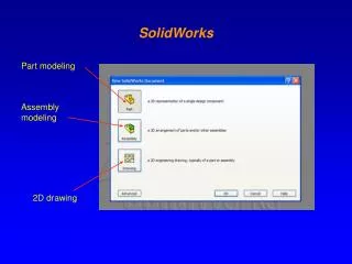
Simple sweep • to create a sweep feature a cross-section and a path are required. • The profile is typically perpendicular to the path, although this is not a requirement. • The profile (cross-section) can change along the path, but the overall shape must remain the same.
Sweep • Sweep is one of the advanced feature in SolidWorks • Sweep can create: • a base, • boss, • cut, • or surface • by definition, moving a profile(section) along a path, will create a sweep feature.
controlling the size, orientation, and position of the cross-section as it travels through the sweep. No trajectory controlled interpolation trajectory controlled interpolation
Sweep Steps of creating a simple sweep feature • Sketch a closed, non-intersecting profile on a plane or a face. • Create the path for the profile to follow. Use a sketch, existing model edges, or curves. • Swept Boss/Base or Swept Cut or Swept Surface • Select a sketch in the graphics area for Profile • Select a sketch in the graphics area for Path
Sweep • Sweeps can: • Use guide curves (more advanced) • Be created with multiple profiles • Be created as thin features
Introducing Guide Curve and Path Path – vertical sketch through ellipse Guide curve – spline Profile - ellipse • Path and guide curve length • The path and the guide curves may differ in length. • If the guide curves are longer than the path, the sweep is as long as the path. • If the guide curves are shorter than the path, the sweep is as long as the shortest guide curve
Pierce constraint Pierce relation • It acts as if the 3D curve is a length of thread and the sketch point is the eye of a needle where the thread pierces the needle eye. • The Pierce relation is most important in the Sweep feature when it is applied in the profile sketch between endpoints, center points, or sketch points and the out-of-plane guide curves. • This is because the Pierce relation determines how the profile sketch will be solved when it is moved down the sweep path to create intermediate profiles.
Solid sweep • cut sweeps • The most common usage is in creating cuts around cylindrical bodies. • This option would also be useful for end mill simulation. Tool body and path Cut sweep sweep cut along a non-tangent path(to check)
Solid sweep • how Solid sweep handles a tool body following a helix path • When you select Follow path for the Orientation/twist type, and None for Path alignment type, the tool body correctly follows the tangents of the helix path
Solid sweep • To keep the tool body perpendicular to a reference as it follows a helix path, • select Direction Vector for Path alignment type, • select a direction to which the tool body remains perpendicular, for example, the normal to the planar end face of a cylinder. • The tool body remains parallel to the end face as it follows the helix path along the cylinder. • - This functionality is important for the tool machining market
Solid sweep • Tool body must: • Be a 360-degree revolved feature. • Contain only analytical geometry, such as lines and arcs • Not be merged with the model. For cut sweeps only, when you select Solid sweep, the path must be tangent within itself (no sharp corners) and begin at a point on or within the tool body profile.
Sweep and solid sweep assignment Orientation/twist type : Follow path Path alignment type : None
A common Loft example • سر چکش زیر را با loft مدل نمایید.
تمرین • مته به قطر خارجی mm 20 را مدل نمایید. کلیه ویژه گی های عملکرد مدل شود. • قطعه زیر impeller را به صورت یک جسم صلب مدل نمایید. سطوح پره فقط با یک سطح مدل شود. کلیه لبه های تیز fillet یا پخ زده شود.
3- با استفاده از دستور solid sweep و منحنی helix با گام متغیر دو نوع پیچ انتقال زیر را ایجاد نمایید. توجه نمایید که نوک ابزار کروی است.