Workshop 3 Room Temperature Study
Workshop 3 Room Temperature Study. Introduction to CFX. Introduction.


Workshop 3 Room Temperature Study
E N D
Presentation Transcript
Workshop 3Room Temperature Study Introduction to CFX
Introduction In this workshop you will be analyzing the effect of computers and workers on the temperature distribution in an office. In the first stage airflow through the supply air ducts will be simulated and the outlet conditions for the duct will be used to set the inlet conditions for the room. Although both components could be analyzed together, separating the two components allows different room configurations to be analyzed without solving the duct flow again.
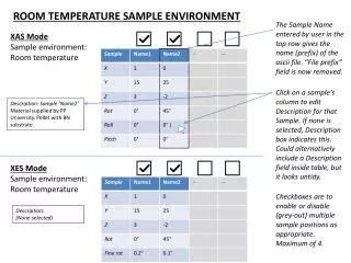
Duct Simulation • The operating conditions for the flow are: • The working fluid is Air Ideal Gas • Fluid Temperature = 21 [C] • Inlet: 0 [atm] Total Pressure • Outlet: 0.225 [kg/s] (per vent) vent2 Inlet vent1
Starting CFX in Workbench • Open Workbench • Drag CFX into the Project Schematic from the Component Systems toolbox • Change the name of the system to duct • Save the project as RoomStudy.wbpj in an appropriate directory • Double-click Setup
Import Mesh • Right-click on Mesh in the Outline tree and select Import Mesh > ICEM CFD • Select the file duct_mesh.cfx5 • Make sure Mesh Units are in m and click Open to import the mesh The first step is to import the mesh that has already been created:
Create Domain • Double-click on Default Domain in the Outline tree to edit the domain • On the Basic Settings tab, set the Fluid 1 Material setting to Air Ideal Gas • Switch to the Fluid Models tab • Set the Heat Transfer Option to Isothermal • Heat Transfer is not modeled, but since the working fluid is an ideal gas we need to provide a temperature so its properties can be calculated • Set the Fluid Temperature to 21 [C] • Change the Turbulence Model Option to Shear Stress Transport • Click OK to commit the changes to the domain You can now create the computational domain:
Create Boundary Conditions • INLET Boundary Condition • Name: INLET • Boundary Type: Inlet • Location: INLET • Mass and Momentum Option: Total Pressure (stable) • Relative Pressure: 0 [Pa] • VENT2 Boundary Condition • Name: VENT2 • Boundary Type: Outlet • Location: VENT2 • Mass and Momentum Option: Mass Flow Rate • Mass Flow Rate: 0.225 [kg/s] Now create the following boundary conditions: • VENT1 Boundary Condition • Name: VENT1 • Boundary Type: Outlet • Location: VENT1 • Mass and Momentum Option: Mass Flow Rate • Mass Flow Rate: 0.225 [kg/s]
The default Conservation Target is 1%. This means that the global imbalance for each equation must be less than 1% (i.e. (flux in – flux out)/flux in < 1%). The solver will not stop until both the Residual Target and the Conservation Target have been met (or Max. Iterations is reached). Solver Control • Double click on Solver Control from the Outline tree • Enable the Conservation Target toggle • Click OK to commit the settings
Monitor Point • Double click on Output Control from the Outline tree • Switch to the Monitor tab and enable the Monitor Options toggle • Under Monitor Points and Expressions, click the New icon • Keep the default name Monitor Point 1 • Set the Option to Expression Monitor points are used to monitor quantities of interest during the solution. They should be used to help judge convergence. In this case you will monitor the velocity of the air that exits through the vent. One measure of a converged solution is when this air has reached a steady-state velocity.
Monitor Point • In the Expression Value field, type in:areaAve(Velocity w)@VENT1 • Click OK to create the Monitor Point
Write Solver File • Close CFX-Pre to return to Project window • Save the project • Right-click on Solution and select Edit • Choose Start Run You can now save the project and proceed to write a definition file for the solver:
CFX Solver Manager • Examine the residual plots for Momentum and Mass and Turbulence • Examine the User Points plot • When the run finished close the Solver Manager • View the results in CFD-Post by double-clicking Results in the Project window Monitor point Residual plot
CFD-Post • Select File > Export • Change the file name to vent1.csv • Use the browse icon to set an appropriate directory • Set Type as BC Profile and Locations as VENT1 • Leave Profile Type as Inlet Velocity and click Save • Similarly export a BC profile of VENT2 to the file named vent2.csv • Quit CFD-Post and return to the Project Schematic Now we will export a Boundary Condition profile from the outlet regions for use in the next simulation.
Operating Conditions • The working fluid is Air Ideal Gas • Computer Monitor Temperature = 30 [C] • Computer Vent Flow Rate: 0.033 [kg/s] @ 40 [C] (per computer) • Ceiling Vents: Profile Data, Temperature=21 [C] The operating conditions for the flow in the room are: outlet vent2 vent1
Starting Room Simulation in Workbench • Drag CFX into the Project Schematic from the Component Systems toolbox • Change the name of the system to room • Double-click Setup in the room system
Import Mesh • Right-click on Mesh in the Outline tree and select Import Mesh > ICEM CFD • Select the file room.cfx5 • Make sure the Mesh Units are in m and click Open to import the mesh The first step is to import the mesh that has already been created:
Enabling Buoyancy allows for natural convection due to density variations. The buoyancy force is a function of density variations relative to the buoyancy reference density. Since density variations can be very small, using a reference density help avoid round-off errors. The reference density should be a typical fluid density in the domain. Create Domain • Edit Default Domain from the Outline tree • On the Basic Settings tab, set the Fluid 1 Material setting to Air Ideal Gas • Set the Buoyancy Option to Buoyant. Set the Buoyancy settings as shown: • Gravity X Dirn. = 0 [ m s^-2 ] • Gravity Y Dirn. = 0 [ m s^-2 ] • Gravity Z Dirn. = -g (first, click the Enter Expression icon ) • Buoy. Ref. Density = 1.185 [ kg m^-3 ] You can now create the computational domain:
For most cases, setting an initial condition for domain temperature is not necessary since the solver can automatically calculate initial conditions. However, if you input a value that is closer to the final solution than what the solver would automatically calculate, you will reach a converged solution faster. Create Domain • Switch to the Fluid Models tab • Change the Heat Transfer Option to Thermal Energy • Change the Turbulence Model Option to Shear Stress Transport • Switch to the Initialisation tab • Check the Domain Initialisation box • Set the Temperature Option to Automatic with Value. Set the Temperature to 21 [C] • Click OK to commit the changes to the domain
Profile data initialization • Select Tools >Initialise Profile Data and choose the Data File as vent1.csv. Click OK • CFX-Pre reads the file and creates functions that point to the variables available in the file (see the User Functions section in the Outline tree). Boundary conditions can be set by referencing these functions. E.g. VENT1.Velocity u(x,y,z) refers to the Velocity u value in the VENT1 function with the local coordinate values x, y and z passed in as the arguments. Any value with the correct dimensions can be passed in as an argument, but usually the local coordinates are used. • Similarly initialise profile data for vent 2 by choosing vent2.csv
Create Boundary Conditions Now create the following boundary conditions: • vent1 Boundary Condition • Name: vent1 • Boundary Type: Inlet • Location: VENT1 • Select Use Profile Data and choose VENT1 as the Profile Name • Click Generate Values • This will create expressions for the Mass and Momentum option on the Boundary Details tab that reference the profile functions • On the Boundary Details tab check that the expressions make sense • Heat Transfer Option: Static Temperature • Static Temperature: 21 [C]
Create Boundary Conditions • vent2 Boundary Condition • Name: vent2 • Boundary Type: Inlet • Location: VENT2 • Select Use Profile Data and choose VENT2 as the Profile Name • Click Generate Values • The Mass and Momentum Option will be automatically updated • Heat Transfer Option: Static Temperature • Static Temperature: 21 [C] • workers Boundary Condition • Name: workers • Boundary Type: Wall • Location: WORKERS • Heat Transfer Option: Temperature • Fixed Temperature: 37 [C]
Create Boundary Conditions • outlet Boundary Condition • Name: outlet • Boundary Type: Opening • Location: OUTLET • Mass and Momentum Option: Opening Pres. and Dirn • Relative Pressure: 0 [Pa] • Heat Transfer Option: Opening Temperature • Opening Temperature: 21 [C] • monitors Boundary Condition • Name: monitors • Boundary Type: Wall • Location: monitors • Heat Transfer Option: Temperature • Fixed Temperature: 30 [C]
Create Boundary Conditions • computerVent Boundary Condition • Name: computerVent • Boundary Type: Inlet • Location: COMPUTER1VENT, COMPUTER2VENT, COMPUTER3VENT, COMPUTER4VENT • Mass and Momentum Option: Mass Flow Rate • Mass Flow Rate: 0.132 [kg/s] • Heat Transfer Option: Static Temperature • Static Temperature: 40 [C]
Create Boundary Conditions • computerIntake Boundary Condition • Name: computerIntake • Boundary Type: Outlet • Location: COMPUTER1INTAKE, COMPUTER2INTAKE, COMPUTER3INTAKE, COMPUTER4INTAKE • Mass and Momentum Option: Mass Flow Rate • Mass Flow Rate: 0.132 [kg/s] • Mass Flow Update Option: Constant Flux • This enforces a uniform mass flow across the entire boundary region, rather than letting a natural velocity profile develop. It is used here to make sure the flow rate through each intake is the same.
Solver Control • Edit Solver Control from the Outline tree • Due to nature of this flow it will take a long time for a steady-state condition to be reached • Increase the Max. Iterations to 750 • Change the Timescale Control to Physical Timescale • Set a Physical Timescale of 2 [s] • Enable the Conservation Target toggle • Click OK to commit the settings
Monitor Point • Edit Output Control from the Outline tree • Switch to the Monitor tab and enable the Monitor Options toggle • Under Monitor Points and Expressions, click the New icon • Enter the Name as temp • Set the Option to Expression Monitor points are used to monitor quantities of interest during the solution. They should be used to help judge convergence. In this case you will monitor the temperature of the air that exits through the outlet. One measure of a converged solution is when this air has reached a steady-state temperature.
Monitor Point • In the Expression Value field, type in:massFlowAve(Temperature)@outlet • Click OK to create the Monitor Point
Write Solver File • Close CFX-Pre to return to the Project window and save the project • Select File > Import from the main menu in Workbench • Set the file filter to CFX-Solver Results File • Select the results file provided with this workshop, room_001.res • Change the name of the system to room results … You can now save the project and proceed to write a definition file for the Solver: The solution will take several hours to solve on one processor. To save time, a results file is provided with this workshop. The Project Schematic shows that the room Solution has not been completed, so you cannot view the results in CFD-Post yet. To view the results for the file provided you’ll need to add the results to the project.
CFX Solver Manager • Right-click on Solution in the room results system and select Display Monitors • Examine the residual plots for Momentum and Mass, Heat Transfer and Turbulence • The Residual Target of 1e-4 was met at about 270 iterations, but the solver did not stop because the Conservation Target had not been met • Examine the User Points plot • Air temperature leaving through the outlet did not start to reach a steady temperature until >650 iterations. Using residuals as the only convergence criteria is not always sufficient. Now you can view the solution for the previously solved case.
Residual and Monitor plot Residual plot Monitor points
CFX Solver Manager • Check the Domain Imbalances at the end of the .out file for each equation • You can right click in the text monitor, select Find… and search for “Domain Imbalance” to find the appropriate section • An imbalance is given for the U-Mom, V-Mom, W-Mom, P-Mass and H-Energy equations • It took 653 iterations to satisfy the Conservation Target of 1% for the H-Energy equation – see the Plot Monitor 1 tab • Close the Solver Manager • View the results in CFD-Post by double-clicking Results in the Project Schematic from the room system
CFD-Post • Select Location > Plane from the toolbar • In the Details windows on the Geometry tab, set the Definition Method to ZX Plane • Set Y to 1.2 [m] • On the Colour tab set Mode to Variable • Set Variable to Temperature • Set Range to Local and click Apply • Observe the temperature distribution (for example, how the warm air collects under the table) Start by creating a ZX Plane at Y = 1.2 [m]
CFD-Post • ZX Plane at Y = 2 [m] • ZX Plane at Y = 5.1 [m] • XY Plane at Z = 0.25 [m] • When finished observing the temperature distribution, uncheck the visibility boxes of the planes that you created Using the same procedure, create several other planes displaying the temperature profile:
CFD-Post • Click Insert > Vector from the main menu • In the Details windows on the Geometry tab, set Location to Plane 2 and Symbols Size to 3.0 in Symbol tab • Click Apply • After observing the flow behavior on Plane 2, switch the Location to Plane 4 Plot vector plots on the planes that you created:
Further Steps (Optional) • Observe the density variation at various planes • Create a streamline from each of the vents • You may want to adjust the values on the Limits tab (Max. Segments) • Animate the streamlines • Right-click on the Streamlines in the 3D viewer and select Animate • Create an isosurface based on different temperatures (e.g., 22 [C], 24 [C], etc.) • Calculate the areaAve of Wall Heat Flux on the workers • Click Tools > Function Calculator Time permitting, you may want to try the following: