3 - Temperature Sensors
3 - Temperature Sensors. 1. Thermoresistive sensors 2. Thermoelectric sensors 3. PN junction temperature sensors Optical and acoustic temperature sensors Thermo-mechanical sensors and actuators. A bit of history. Temperature measurements and thermometers


3 - Temperature Sensors
E N D
Presentation Transcript
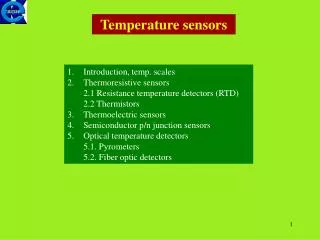
3 - Temperature Sensors 1. Thermoresistive sensors 2. Thermoelectric sensors 3. PN junction temperature sensors Optical and acoustic temperature sensors Thermo-mechanical sensors and actuators
A bit of history • Temperature measurements and thermometers • 1600 - thermometers (water expansion, mercury) • 1650 - first attempts at temperature scales (Boyle) • 1700 - “standard” temperature scales (Magelotti, Renaldini, Newton) - did not catch • 1708 - Farenheit scale (180 div.) • 1742 - Celsius scale • 1848 - Kelvin scale (based on Carnot’s thermodynamic work) • 1927 - IPTS - International Practical Temperature Scale
More history - sensors • Temperature sensors are the oldest sensors • 1821 - Seebeck effect (Thomas Johann Seebeck) • 1826 - first sensor - a thermocouple - based on the Seebeck effect (Antoine Cesar Becquerel) • 1834 - Peltier effect (Charles Athanase Peltier). • First peltier cell built in 1960’s • Used for cooling and heating • 1821 - discovery of temperature dependence of conductivity (Sir Humphrey Davey) • 1871 - William Siemens builds the first resistive sensor made of platinum
Temperature sensors - general • Temperature sensors are deceptively simple • Thermocouples - any two dissimilar materials, welded together at one end and connected to a micro-voltmeter • Peltier cell - any thermocouple connected to a dc source • Resistive sensor - a length of a conductor connected to an ohmmeter • More: • Some temperature sensors can act as actuators as well • Can be used to measure other quantities (electromagnetic radiation, air speed, flow, etc.) • Some newer sensors are semiconductor based
Temperature sensors - types • Thermoelectric sensors • Thermocouples and thermopiles • Peltier cells (used as actuators but can be used as sensors) • Thermoresistive sensors and actuators • Conductor based sensors and actuators (RTDs) • Semiconductor based sensors - thermistors, diodes • Semiconductor junction sensors • Others • Based on secondary effects (speed of sound, phase of light) • Indirect sensing (infrared thermometers - chapter4) • Expansion of metals, bimetals
Thermal actuators • A whole class of thermal actuators • Bimetal actuators • Expansion actuators • Thermal displays • Sometimes sensing and actuation is combined in a single device
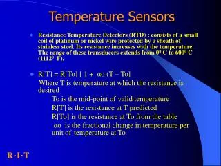
Thermoresistive sensors • Two basic types: • Resistive Temperature Detector (RTD) • Metal wire • Thin film • Silicon based • Thermistors (Thermal Resistor) • NTC (Negative Temperature Coefficient) • PTC (Positive Temperature Coefficient)
Thermoresistive effect • Conductivity depends on temperature • Conductors and semiconductors • Resistance is measured, all other parameters must stay constant.
Thermoresistive effect (cont.) • Resistance of a length of wire • Conductivity is: • Resistance as a function of temperature: • a - Temperature Coefficient of Resistance (TCR) [C]
Thermoresistive effect (cont.) • T is the temperature [C ] • 0 is the conductivity of the conductor at the reference temperature T0. • T0 is usually given at 20C but may be given at other temperatures as necessary. • a - Temperature Coefficient of Resistance (TCR) [C] given at T0
Example • Copper: 0=5.9x10⁷ S/m, =0.0039 C at T0=20C. Wire of cross-sectional area: 0.1 mm2, length L=1m, • Change in resistance of 6.61x10/C and a base resistance of 0.017 at 20C • Change of 0.38% per C .
Example (cont.) • Conclusions from this example: • Change in resistance is measurable • Base resistance must be large - long and/or thin conductors or both • Other materials may be used
Other considerations • Tension or strain on the wires affect resistance • Tensioning a conductor, changes its length and cross-sectional area (constant volume) • has exactly the same effect on resistance as a change in temperature. • increase in strain on the conductor increases the resistance of the conductor (strain gauge) • Resistance should be relatively large (25W and up)
Construction - wire RTD • A spool of wire (length) • Similar to heating elements • Uniform wire • Chemically and dimensionally stable in the sensing range • Made thin (<0.1mm) for high resistance • Spool is supported by a glass (pyrex) or mica support • Similar to the way the heating element in a hair drier is supported • Keeps strain at a minimum and allows thermal expansion • Smaller sensors may not have an internal support. • Enclosed in a glass, ceramic or metal enclosure • Length is from a few cm, to about 50cm
Construction (cont.) • Materials: • Platinum - used for precision applications • Chemically stable at high temperatures • Resists oxidation • Can be made into thin wires of high chemical purity • Resists corrosion • Can withstand severe environmental conditions. • Useful to about 800 C and down to below –250C. • Very sensitive to strain • Sensitive to chemical contaminants • Wire length needed is long (high conductivity)
Construction (cont.) • Materials: • Nickel and Copper • Less expensive • Reduced temperature range (copper only works up to about 300C) • Can be made into thin wires of high chemical purity • Wire length needed is long (high conductivity) • Copper is not suitable for corrosive environments (unless properly protected) • At higher temperatures evaporation increases resistance
This is unrelated to the course - just a curiosity - close-up
Thin Film RTDs • Thin film sensors: produced by depositing a thin layer of a suitable material (platinum or its alloys) on a thermally stable, electrically non-conducting, thermally conducting ceramic • Etched to form a long strip (in a meander fashion). • Eq. (3.1) applies but much higher resistance sensors are possible. • Small and relatively inexpensive • Often the choice in modern sensors especially when the very high precision of Platinum wire sensors is not needed.
Tnin film RTDs - (cont.) • Two types of thin film RTDs from different manufacturers • Dimensions are typical - some are much larger
Some parameters • Temperature range: -250 C to 700 C • Resistances: typically 100W (higher available) • Sizes: from a few mm to a few cm • Compatibility: glass, ceramic encapsulation • Available in ready made probes • Accuracy: ±0.01 C to ±0.05 C • Calibration: usually not necessary beyond manufacturing
Self heat in RTDs • RTDs are subject to errors due to rise in their temperature produced by the heat generated in them by the current used to measure their resistance • Wire wound or thin film • Power dissipated: Pd=I2R ( I is the current (RMS) and R the resistance of the sensor) • Self heat depends on size and environment • Given as temperature rise per unit power (C/mW) • Or: power needed to raise temperature (mW/ C)
Self heat in RTDs (cont.) • Errors are of the order of 0.01C/mW to 10C/mW (100mW/C to 0.1mW/C) • Given in air and in water • In water values are lower (opposite if mW/C used) • Self heat depends on size and environment • Lower in large elements, higher in small elements • Important to lower the current as much as possible
Response time in RTDs • Response time • Provided as part of data sheet • Given in air or in water or both, moving or stagnant • Given as 90%, 50% (or other) of steady state • Generally slow • Wire RTDs are slower • Typical values • 0.5 sec in water to 100 sec in moving air
Silicon Resistive Sensors • Conduction in semiconductors • Valence electrons • Bound to atoms in outer layers (most electrons in pure semiconductors) • Can be removed through heat (band gap energy) • When removed they become conducting electrons (conduction band) • A pair is always released - electron and hole • Conductivity of semiconductors is temperature dependent • Conductivity increases with temperature • Limited to a relatively small temperature range
Silicon Resistive Sensors (cont.) • Pure silicon: • NTC device - negative temperature coefficient • Resistance decreases with temperature • Resistance in pure silicon is extremely high • Need to add impurities to increase carrier density • N type silicon - add arsenic (As) or antimony (Sb) • Behavior changes: • Resistance increases up to a given temperature (PTC) • Resistance decreases after that (NTC) • PTC up to about 200 C
Silicon resistive sensors • Silicon resistive sensors are somewhat nonlinear and offer sensitivities of the order 0.5-0.7 %/C. • Can operate in a limited range of temperatures like most semiconductors devices based on silicon • Maximum range is between –55C to +150C. • Typical range: - 45C to +85C or 0C to +80C • Resistance: typically 1k at 25 C. • Can be calibrated in any temperature scale • Made as a small chip with two electrodes and encapsulated in epoxy, metal cans etc.
Thermistors • Thermistor: Thermal resistor • Became available: early 1960’s • Based on oxides of semiconductors • High temperature coefficients • NTC • High resistances (typically)
Thermistors (cont.) • Transfer function: • [] and [K] are constants • R(T): resistance of the device • T: temperature in K • Relation is nonlinear but: • Only mildly nonlinear (b is small) • Approximate transfer function
Construction • Beads • Chips • Deposition on substrate
Thermistors - properties • Most are NTC devices • Some are PTC devices • PTC are made from special materials • Not as common • Advantageous when runaway temperatures are possible
Thermistors - properties • Self heating errors as in RTDs but: • Usually lower because resistance is higher • Current very low (R high) • Typical values: 0.01C/mW in water to 1C/mW in air • Wide range of resistances up to a few MW • Can be used in self heating mode • To raise its temperature to a fixed value • As a reference temperature in measuring flow • Repeatability and accuracy: • 0.1% or 0.25C for good thermistors
Thermistors - properties • Temperature range: • - 50 C to about 600 C • Ratings and properties vary along the range • Linearity • Very linear for narrow range applications • Slightly nonlinear for wide temperature ranges • Available in a wide range of sizes, shapes and also as probes of various dimensions and shapes • Some inexpensive thermistors have poor repeatability - these must be calibrated before use. • Overall much less expensive than RTDs
Thermoelectric sensors • Among the oldest sensors (over 150 years) • Some of the most useful and most common • Passive sensors: they generate electrical emfs (voltages) directly • Measure the voltage directly. • Very small voltages - difficult to measure • Often must be amplified before interfacing • Can be influenced by noise
Thermoelectric sensors (cont.) • Simple, rugged and inexpensive • Can operate on almost the entire range of temperature from near absolute zero to about 2700C. • No other sensor technology can match even a fraction of this range. • Can be produced by anyone with minimum skill • Can be made at the sensing site if necessary
Thermoelectric sensors (cont.) • Only one fundamental device: the thermocouple • There are variations in construction/materials • Metal thermocouples • Thermopiles - multiple thermocouples in series • Semiconductor thermocouples and thermopiles • Peltier cells - special semiconductor thermopiles used as actuators (to heat or cool)
Thermoelectric effect • The Seebeck effect (1821) • Seebeck effect is the sum of two other effects • The Peltier effect • The Thomson effect • ThePeltier effect: heat generated or absorbed at the junction of two dissimilar materials when an emf exists across the junction due to the current produced by this emf in the junction. • By connecting an external emf across the junction • By the emf generated by the junction itself. • A current must flow through the junction. • Applications in cooling and heating • Discovered in 1834
Thermoelectric effect (cont.) • The Thomson effect (1892): a current carrying wire if unevenly heated along its length will either absorb or radiate heat depending on the direction of current in the wire (from hot to cold or from cold to hot). • Discovered in 1892 by William Thomson (Lord Kelvin).
Thermoelectric effect (cont.) • The Seebeck effect: an emf produced across the junction of two dissimilar conducting materials connected together. • The sum of the Peltier and the Thomson effects • The first to be discovered and used (1821) • The basis of all thermoelectric sensors • Peltier effect is used in Thermoelectric Generators (TEG) devices
The Seebeck effect • If both ends of the two conductors are connected and a temperature difference is maintained between the two junctions, a thermoelectric current will flow through the closed circuit (generation mode)
The Seebeck effect • If the circuit is opened an emf will appear across the open circuit (sensing mode). It is this emf that is measured in a thermocouple sensor.
Themocouple - analysis • Conductors a, b homogeneous • Junctions at temperatures T2 and T1 • On junctions 1 and 2: • Total emf:
Thermocouple - analysis • A and B are the absolute Seebeck coefficients given in V/C and are properties of the materials A, B • AB=A-B is the relative Seebeck coefficient of the material combination A and B, given in V/C • The relative Seebeck coefficients are normally used.