Temperature Sensors
510 likes | 999 Vues
Temperature Sensors. ECE 371 JB Prof. Bernhard. A Simple Thermal System. Sensor. Work Load. Temperature Controlling Device. Heat Source. Sensor Input. Output. Types. Thermocouples Resistance temperature devices (RTD) Thermistors Infrared sensors. Thermocouples.

Temperature Sensors
E N D
Presentation Transcript
Temperature Sensors ECE 371 JB Prof. Bernhard
A Simple Thermal System Sensor Work Load Temperature Controlling Device Heat Source Sensor Input Output
Types • Thermocouples • Resistance temperature devices (RTD) • Thermistors • Infrared sensors
Thermocouples • Mostly widely used in industry • Range: sub-zero to 4000oF(2000oC) • Formed by joining two different metal alloy wires (A,B) at point called junction • Junction called the measuring or “hot” junction • Lead ends attached to temp indicator or controller • Connection point called reference or “cold” junction Display Device Measuring Junction A + - B Reference Junction
How does it work? • Measuring junction is heated, small DC voltage (millivolts) generated in thermocouple wires • Thermocouple converts thermal energy into electrical energy • Note: thermocouple only generates a millivoltage signal when there is temperature difference between “hot” and “cold” junctions • “cold” junction usually set to 32oF(0oC)
Thermocouple Types • Made up of two different metal alloy wires. • Different alloys result in different temperature ranges Ex:
Pros/Cons • Each thermocouple type has advantages & disadvantages • Cost: • Rare metals (i.e. noble metals) $$$ • Types B, R, S • Common metals (i.e. base metals) $ • Types E, J, K, N, T • Rarer metals = high temperature range & better accuracy • Temperature Range • Accuracy a.k.a. tolerance • Life Expectancy • Operating Temp. • Wire size • Thermocouple protection • Environment • Accuracy required
Life Expectancy • Failed = inaccuracy • When wires are heated/cooled changes take place on molecular level • Physically: molecular structure changes • Chemically: wires react with oxygen or other substances, changing chemical composition • Result: millivolt signal “drifts” EMF (mV) Tolerance Band Time - Recalibration: adjust controller to compensate for errors
Thermocouple Constructions • 3 General constructions • Insulated Wire • Ceramic-beaded • Metal-sheathed
Insulated Wire Thermocouples • Bare wires wrapped with insulation • Insulations • Fibrous, woven material made of fiber-glass, mica, or ceramic fiber • Plastics (Teflon) • Polyimides (Kapton) • Purpose • Electrically isolate wires • Protects wires from contamination • Easier wire installation
Metal - Sheathed Thermocouples • Junction and wires are assembled in small diameter metal tubes • Insulation • Fiberglass • MgO • Purpose • Protects against contamination • Defends against chemical attack • Provides mechanical stability
Metal - Sheathed Thermocouples Orientation of thermocouple junction during assembly • Grounded • Weld junction directly to inside tip of sheath • Ensures rapid heat transfer from sheath to junction • Protects junction while minimizing heat transfer delays. • Ungrounded • Similar to grounded except junction isolated from metal sheath • Electrically isolates junction from sheath • Prevents stray voltages from inducing measuring error • More shock resistant & better under rapid temperature changes • DISADVANTAGE: Slows down heat transfer to junction (2x-3x slower) • Exposed • Junction protrudes from end of sheath, but insulated from it • Due to direct exposure with heated material, very quick response to temp. changes • No sheath to slow down heat transfer • DISADVANTAGE: Not protected from mechanical damage & chemical attack
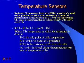
Resistance Temperature Devices (RTD) • Precision Temperature Sensors • More accurate than thermocouple elements • Maintain accuracy over longer period of time • Range up to 1200oF (650oC) • Styles • Wire-Wound • Thin film • Kapton Insulated
How do RTDs work? • RTD’s resistance as temp. • Controller measures resistance value and converts to temp. reading, fairly linear relationship. • Unlike thermocouple, no electrical signal generated • Controller measures resistance by passing current through RTD • Use a base resistance value (ex: for Platinum, value of 100 ohms at 0oC (32oF) RTD Resistance Vs. Temp. (TCR) Curve Resistance (Ohms) TCR = Temperature coefficient of resistance Temperature (oC)
RTD Vs. Thermocouples • Advantages of RTDs • Stability • Repeatability • Accuracy • Disadvantages of RTDs • Cost: Platinum = $$$, 2x more expensive • Temp. Range limited • Response Time slower, 2x-4x times slower • Heat must transfer through epoxy or glass coating • Entire RTD element must reach uniform temp. before accurate measurement taken.
Lead Wire Effect • Alters reading due to lead wire resistance • Two approaches • Determine lead wire resistance and have controller compensate • Attach additional lead wire to one end of RTD • Connect a transmitter, converts resistance to low amp signal and sent to temperature controller 2 3 1 3 4 1 2 3-wire RTD 4-wire RTD RTD RTD
Effect of Lead Resistance: Platinum Wire RTD • Most Common: DIN 43760 • Standard temp. coefficient (alpha=0.00385) • For 100 ohm wire +0.385 ohms/OC @ 0oC • alpha = average slope from 0oC – 100oC • A 10 ohm lead impedance implies 10/3.85 = 26oC error in measurement R=5 R=5 Lead 100 RTD Lead R=5
How to correct this problem? • Wheatstone: 3-Wire Bridge • Wires A & B are perfectly matched in length, respective impedances effects will cancel out due to being on opposite legs • Wire C acts as sense lead & carries no current A DVM C RTD B • Non-linear relationship between resistance change and bridge output voltage change • Additional equation required to convert bridge output voltage to equivalent RTD impedance
3-Wire Bridge Calculations • If Vs & Vo known, Rg can be found. • Unbalanced Vo of bridge with R1=R2 • If Rg=R3 Vo=0 & bridge is balanced • To determine Rg assuming lead resistance is zero
3-Wire Bridge Calculations • If Rg located some distance from 3-wire configuration RL appears in series with Rg & R3 RL Rg + + - V3/2 - Vo RL
Another Approach • 4-Wire Ohms • DVM is directly proportional to RTD resistance 1 conversion equation required • Insensitive to length of lead wires • Accuracy better than 3-wire • Disadvantage: One more extension wire required. + Current Source i = 0 100 W RTD DVM i = 0 - RTD=Rg + - + Vs - Vo
Resistance to Temperature Conversion • RTD more linear than thermocouple, curve-fitting still required • Callendar-Van Dusen Equation RT = Resistance at Temperature T Ro = Resistance at T=0oC = Temperature coefficient at T=0oC = 1.49 (typical value for 0.00392 platinum) = 0 T>0, 0.11 (typical) T<0
Identification • 2-wire RTD uses same color lead wire for both leads • 3-wire has 2 red leads & 1 white lead • 4-wire has 2 red leads & 2 white leads 3 4 1 2 4-wire RTD RTD
RTD Assembly • Wire Wound • For 500oF (260oC), element welded to copper or nickel lead wires • Sub-assembly placed in closed-end tube • Powder, cement or thermal grease fills tube • Epoxy seal seals out moisture & locks RTD/leads to tube • Thin Film • For 1200oF (650oC), element fitted into cavity of MgO metal-sheathed cable • Wires in cable welded to RTD element • Cap filled with MgO and placed on element end & mounted
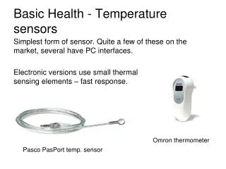
What are Thermistors? • Semiconductor used as temperature sensor • Made from mixture of metal oxides pressed to bead or wafer form • Bead heated under pressure at high temp & encapsulated with glass/epoxy • RESULT: Distinct non-linear resistance vs. temp. relationship Non-linear decrease in resistance as temperature increases. Resistance (Ohms) Temperature (oC)
So Sensitive… • Very large resistance change = small temp. change • 3 – 5% per oC (vs. 0.4% per oC for RTDs) • Temp. changes as small as 0.1oC • Significantly smaller in size • Temp range: -100oC – 300oC (-120oF – 570oF)
Thermistor Standards • No Industrial Standards • Base resistance range: 103 – 106 ohms • Typically measured at 25oC vs. 0oC for RTDs • TCRs vary widely • Thermistor’s accuracy limited to small temp. range
Thermistor Lead Wire Effects • Lead wire does add overall resistance • NOTE: base resistance of thermistor very large (>103 ohms), added lead wire resistance insignificant. • RESULT: No resistance compensation required!
Infrared Sensors • Intercepts portion of infrared energy radiated by object ( = 8 - 14 microns). • Waves focused through lens on infrared detector, converting to an electric output signal Non-Contact Temp. Sensor Heat Source Temp. Indicator Optics Infrared Detector
Emissivity • Def: The ability of a material to radiate or absorb electromagnetic waves. Higher = Better! • Ex: Given values below & emissivity varies by 0.05, what is measuring error? Ans: IR Sensor A 5.5% (0.05/0.9) IR Sensor B 10% (0.05/0.5) IR Sensor A IR Sensor B e = 0.9 e = 0.5
Field of View • All infrared radiation in this filed of view will be detected by the sensor 4.5 in (114 mm) 2.5 in (64 mm) 1.4 in (36 mm) 1.0 in (25 mm) 0.75 in (19 mm) 0.60 in (15 mm) Infrared Sensor 25 mm 76 mm 152 mm
Good vs. Bad Radiation • Position 1, IR sensor sees both target object & background objects • Position 2, IR sensor only sees target object. True target temperature can now be measured. • RULE: target size should be at least 1.5 to 2 times the “spot size.” 2 1 Infrared Sensor Correct Target Placement Incorrect Target Placement Background “Noise”
Scenarios to Avoid • Figure 1: Thin film materials & background radiation enter sensor • Figure 2: Polished metals will not function well with infrared sensing due to the reflecting radiation. Infrared Sensor Infrared Sensor Figure 2 Figure 1
Sensor to Target Distance • To reduce reflected radiant energy, set IR sensor at right angle with respect to target • If space limitation, mount IR up to a maximum of 45O Sensor <45o Product
Operating Environment • Smoke, dust vapors absorb or reflect infrared radiation before getting to sensor lens. • Causes controller to maintain target at wrong temperature Target Infrared Sensor Smoke or Vapors