Temperature sensors
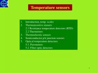
Temperature sensors. Introduction, temp. scales Thermoresistive sensors 2.1 Resistance temperature detectors (RTD) 2.2 Thermistors 3. Thermoelectric sensors 4. Semiconductor p/n junction sensors Optical temperature detectors 5.1. Pyrometers 5.2. Fiber optic detectors. Introduction.

Temperature sensors
E N D
Presentation Transcript
Temperaturesensors • Introduction, temp. scales • Thermoresistive sensors • 2.1 Resistance temperature detectors (RTD) • 2.2 Thermistors • 3. Thermoelectric sensors • 4. Semiconductor p/n junction sensors • Optical temperature detectors • 5.1. Pyrometers • 5.2. Fiber optic detectors
Introduction • From historical point of view the most widely used phenomenon for temperature sensing was expansion (mercury thermometers). • At present one uses detectors with electrical signal at the output. • Temperature detectors can be classified basing of several criteria. • From the point of view of generated power we have: • generation-type sensors (eg. thermoelectric) • parametric-type (eg. resistance R(T), magnetic μ(T), dielectric ε(T)) • From the point of view of other criterion we have: • contact-type sensors (eg. thermoresistors) • noncontact sensors (eg. pyrometers) • In practice we expect that temp. sensors will be: • accurate (for a given temp. range) • reliable (important in process control) • inexpensive (in consumer applications)
Growing perspectives of temperature sensors: • expansion of layer technologies and micromachining • increased application of fiber optic sensors • increased role of microprocessors and sensors with digital output. • Temperature scales • Celsius scale (1742) • Based on two equilibrium points of water: freezing (00C) and boiling (1000C) • Thermodynamic scale • Based on the Carnot engine • T = Ttr· Q/Qtr Q – heat absorbed from the source of temp.T • Qtr – heat discharged to the source of temp. • Ttr= 273.16 K • International Temperature Scale 1990 (ITS90) • Based on thermodynamic scale which is conneted with Celsius scale as follows: • t(oC) = T(K) – 273,15 then 1oC = 1K. • There are introduced 17 fixed points (phase equilibrium points) with defined temperatures, interpolation formulae between the fixed points and 4 standard thermometers for temperature measurements. For example between the triple point of equilibrium hydrogen (13.8033K) and the freezing point of silver (961.78 0C) T90 is defined by meansof platinum resistance thermometer.
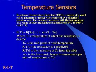
Thermoresistive sensors Thermoresistive sensors can be divided into metallic - type, called RTD (resistance temperature detectors) and semiconductor - type known as thermistors. Metallic temperature detectors (RTDs) The resistance of metallic snsors in a narrow temp. range can be given as a linear dependence: R(t) = Ro[1 + α(t - to)] α – temp. coefficient of resistance TCR Ro – resistance at to (mostly 0oC or 25oC) In a wider temp. range higher order polynomials should be used. For example for platinum the good approximation in a range fom 00C to 8500C is a second order polynomial (PN-EN 60751 in accordance with ITS90): R(Ω) = Ro(1 + 39,083·10-4 T – 5,775 ·10-7 T2) Ro – resistance at 00 C T – temp. in Kelvin scale
RTDs, cont. • The requirements for metallic thermoresistors are as follows: • high sensitivity, i.e. high α • linearity (constant α ) • miniaturization (high resistivity ρ) • chemical inertness and long-term stability Resistivities and TCR for selected metals
Platinum resistance thermometers Platinum is the most popular material for resistance thermometers. Pure Pt is obtained in a form of wires with a diameter lower than 0.05mm, what is necessary to obtain the required magnitude of a thermometer resistance. A lot of possibilities give thin and thick film technologies, which reduces the sensor fabrication costs. Typical Pt sensor is known as Pt100 (100 Ω at 0oC). Relative resistance of a platinum wire given as: R100/Ro = 1 + αΔt is a measure of TCR and depends on wire purity. For a very pure Pt wire one obtains: R100/Ro = 1,3927 in a precise thermometry one uses: R100/Ro = 1,3910
Platinum resistance thermometers In USA SAMA standard for Pt α value specifies : R100/Ro = 1,3925 In Eurpe the standard for Pt thermometers in technical applications (DIN 43760, IEC 751) is: R100/Ro = 1,3850 IEC standard defines additionally two classes of precision for Pt thermometers: A for the range -200 do 650oC (more rigorous) possible error [oC]: ±(0,15 + 0,002|t|) B for the range -200 do 850oC possible error [oC]: ±(0,3 + 0,005|t|). Typical dimensions of Pt wire thrmometers: 3,2 x 10 mm dla 100 Ω, 500 Ω, 1000 Ω 2 x 10 mm dla 100 Ω, 500 Ω, 1000 Ω 2 x 2,5 mm dla 100 Ω 1 x 5 mm dla 100 Ω Outside view of Pt wire thermometers
Thin film Pt sensors Thin film of Pt is deposited on the ceramic substrate and the resistance corrected for the required magnitude. Laser cut thin film of platinum with bonded lead wires (view of a sensor without covering protective layers). Ready for use thin film Pt thermometer
Semiconductor resistance temperature sensors (thermistors) Thermistors are mostly obtained as sintered oxides, sulfides and selenides of elements such as Co, Mn, Ti, Fe, Ni, Cu, Al, fabricated in a form of bars, droplets, discs and also thick films. Thermistors can be divided into two groups: NTC (negative temperature coefficient) PTC (positive temperature coefficient). Characteristics of NTC and PTC thermistors as compared to metallic RTD thermoresistors.
NTC thermistors Conventional oxide resistors have a negative TCR and their resistance as a function of temperature can be written with a good approximation as: RT = A exp [β/ T] Constant A depends on sample dimensions, β is a material constant which determines the sensitivity (β = 3000 – 4500K). Introducing the reference resistance Rref at a reference temp. Tref = 25oC, one obtains RT = Rref exp [β(1/T – 1/Tref)] The values of Rref vary in a range: 500Ω – 10MΩ. In a wide temp. range the sensitivityis better characterised by TCR: α = 1/RT· dRT/dT = - β/T2 The values of α are ca. 6 – 10 times higher than those for metals but decrease quickly with temperature.
Measurements of thermoresistors resistance Compensation of leads resistance (in this case 1 and 3) 1,2,3 – identical thermoresistor leads
Thermoelectric sensors For this kind of sensors the generated thermo EMF is based on the Seebeck effect. Seebeck effect (1821) In a circuit consisting of two conductors A and B, which junctions have temperatures T + ΔT and T, the thermoelectric voltage is generated and a thermoelectric current is flowing. A(+) – metal A positive in respect to B For a given conductor the absolute Seebeck coefficient is defined as: and connects the generated electric field Eawith temperature gradient
Thermocouples As the thermocurrent flows in a circuit consisting of at least two different conductors, the differential Seebeck coefficient is introduced and accordingly For the small temperature change we can then write If temperature T0 of the reference junction is known then from the measurement of thermovoltage V the temperature T of a measurement junction can be determined (thermocouple). In practice we do not use α which is temperature dependent but in calculation of a thermovoltage for a given thrmocouple we exploit the tabulated values. Example: Calculate the thermovoltage for Au-Pd thermocouple in the caset0 = 00C, t = 2000C: given thermovoltage for a junction Au-Pt: +1,84 mV given thermovoltage for a junction Pd-Pt : - 1,23 mV Calculated thermovoltage for Au-Pd thermocouple: 1,84 – (-1,23)= 3,07 mV
Thermocouples • Thermocouples widely used are standardised. They are manufactured from alloy materials with compositions which are often restricted by the producer. • Designation (ANSI)Materials • E Chromel/Constantan • J Fe/Constantan • K Chromel/Alumel, known also as NiCr/NiAl • T Cu/Constantan • R Pt/Pt-13%Rh • S Pt/Pt-10%Rh • B Pt-6%Rh/Pt-30%Rh • Properties of K-type thermocouple: • 1-st thermoelectrode NiCr (+), composition: 85% Ni, 12% Cr and other elements in • small quantities • 2-nd thermoelectrode NiAl (-), composition: 95% Ni, 2% Al, 2% Mn, 1% Si, • nearly linear thermometric characteristics, • resistant to oxidizing atmosphere, at elevated temperatures sensitive to reducing • atmosphere, • working temp. range from – 2700C to 11500C, average sensitivity 41 μV/K.
Thermocouples Typical thermocouples are manufactured in insulation. With the help of micromachining technology the thermocouples are manufactured on membranes. The small heat capacity and good thermal isolation enable the registration of infrared radiation spectra. In the solution shown in the figure the cold junction is placed in the area of a good heat conductivity. The hot junction is placed in a central part of a membrane with low thermal conductivity. Additionaly the hot junction is placed under the IR absober. Serial connection of thermocouples, called the thermopile, enhances the sensitivity.
Measurements with the help of thermoelements The basic measurement circuit of a thermocouple. Reference junction temperature variation introduces the measurement error. In a reference temp. 00C one measures εt. In a reference temp. tr one measures εa= εt - εr Compensation of reference temperature variation • The reference junction is put at a distance from the heat source with the help of • compensation leads • PX, NX - the leads with thermoelectrical properties identical with those of thermoelements • (for PtRh-Pt one uses alloys of copper and nikel).
Compensation of reference temperature variation, cont. 2. One uses a thermostat stabilising the reference temp., eg. 500C . Traditionally a reference ice bath was used to maintain 00C, which presents some limitations for the practical uses. 3. Automatic correction of the influence of reference temperature variation The reference temp. increases from t0 to t1 . Response of a thermometer: Rt = R0 [1 + α (t1 – t0)] Response of a thermocouple: Δε = k (t1 – t0) Compensation condition: Δε = - UN The compensation condition is fulfilled if Uz = 4k/α 4. Actual temperature is calculated by a microprocessor as: t = td + C tr td , tr– measured temp., C – thermocouple constant
Pyrometers • This kind of thermometers is used for distant (noncontact)measurements of temperature. • It is based on the analysis of thermal radiation emitted by the objects. • Monochromatic pyrometers are used as standard thermometers from the freezing temp. of silver (961,780C). • Classification of pyrometers: • total radiation pyrometers (wide bandwidth) • monochromatic pyrometers • two-color pyrometers • multicolor pyrometers • Basic laws of thermal radiation • Planck’s law • Radiation flux density, i.e. power of radiation per unit of area and unit of wavelength • (Wm-2µm-1) is equal: • λ- wavelength, c1,c2 – radiation constants • ελ –monochromatic emissivity of a source (for a blackbody equal 1)
Pyrometers, cont. • Stefan-Boltzmann law • Radiation is absorbed by the detector in a limited range of wavelength. Integration of the Planck’s formula vs. wavelength gives a power per unit of area which is emitted by the object with temperature T • σ = 5.67x10⁻⁸ W/m2K4 • ε - emissivity, depending on • the surface condition and temperature • Above formulae, called S-B law, is a base of the wide • band pyrometry. • In the analysis of radiation exchange between • an object and a sensor the radiation reflected • and emitted by the sensor must be taken into • account. This leads to the dependence: • εS, TS – emissivity and temp. • of a sensor
Two color pyrometer The analysis of radiation flux density Φλ as a function of source emissivity ε indicates, that for neighbour wavelength one can write Therefore measurement of a signal in two neighbour narrow spectral ranges elliminates the necessity of determination the source emissivity ε. This is a base of the so called two color pyrometry. Emission spectrum for the source at temperature of 600oC and for three different emissivities ε
Pyrometers construction Two color pyrometer Wide band pyrometer Thermal detectors are used (bolometers or thermopiles). Wide band entrance window is necessary. For this purpose photonic detectors (photovoltaic or photoconductive) are developed, λ1, λ2 – determine narrow bands placed in a neighbourhood. Four colour pyrometers were developed for uses where the emissivity is very low and not stable during processing. Four color pyrometers measure the radiation intensity simultaneously in four different spectral areas and they are able to adapt and make a correction of the emissivity setting.
p/n junction as temperature sensor Semiconductor p/n junction (of eg. diode connected transistor) is polarized in a forward direction. I = IS [exp(qUBE/kT) – 1] for qUBE >> kT UBE = (kT/q) ln (I/IS) = f(T) for I = const one obtains quite good linearity in a range from - 500C to + 1500C For silicon bipolar transistors the sensitivity is equal ∂UBE/ ∂T ≈ - 2,25 mV/K for T=300 K and I=10 μA However the saturation current IS depends weakly on temperature which gives the nonlineatity error. This error is quite small and in many cases no linearity correction is required. Better linearity one obtains in a differential configuration.
p/n junction as temperature sensor, cont. Voltage drops at the junctions powered from constant current sources are equal The differential voltage is equal For a given technology of transistors one can assume that emitter current densities are equal JS1 = JS2. Labelling the emitters cross-sections ratio as r = AS2/AS1 one obtains For IF1 = IF2 and r = 4 one gets:
Junction as temperature sensor, integrated circuit The circuit in the figure illustrates the practical solution of the described differential method employing semiconductor p/n junctions. This system is often manufactured as integrated ciruit in a silicon substrate in monolithic sensors requiring temperature compensation (eg. in micromechined membrane of pressure sensors). Transistors Q3 i Q4 form the so called current mirror which secures the equality of currents IC1 = IC2= I Drop of voltage VT on resistor R is equal and then is proportional to the absolute temperature. The sensors of this type are called PTAT (proportional–to-absolute-temperature) sensors.
Optical temperature sensors Fiber optic detector With the increse of temperature, semiconductor absorption edge shifts to the longer wavelengths and the transmitted light intensity decreases. Emission spectrum of the source diode is also shown. Light intensity decreases after passing the seniconductor.