Download
1 / 24
240 likes | 265 Vues
Areas of application Test pumps are used in generating pressure for the testing, adjusting and calibrating of mechanical and electronic pressure measuring instruments by means of comparative measurements. These pressure tests can be carried out in laboratories, workshops or on site at the set measuring point. Ease of operation When the device under test and a suitably accurate reference measuring instrument are connected to the test pump, after actuating the pump, the same pressure will act on both measuring instruments. Calibration or adjustment of the device under test can be carried out by comparing the two measured values at any pressure value. In order to enable the accurate generation of the measuring points, the test pump is fitted with a fine adjustment valve.<br>For More Information visit on:- www.seeautomation.com<br>Our Mail I.D:- sales@seeautomation.com<br>Contact Us:- 91-11-22012324 , 8144883403<br>

E N D
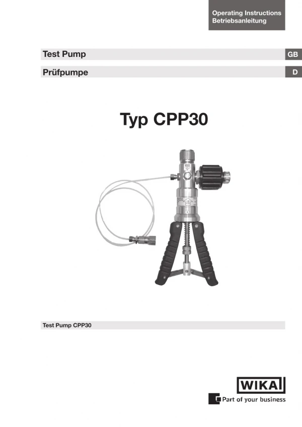
Operating Instructions Betriebsanleitung Test Pump GB Prüfpumpe D Typ CPP30 Test Pump CPP30
Test Pump CPP30 Operating Instructions Test Pump Page 3 - 12 GB Betriebsanleitung Prüfpumpe Seite 13 - 22 D 11044608.02 07/2006 D/GB WIKA Betriebsanleitung Hand-Held Thermometer WIKA Operating Instructions Test Pump 2
Test Pump CPP30 Contents Contents GB 1. Safety Instructions 4 2. Product Description 4 3. Mounting Instructions 5 4. Operation of the Test Pump 6 4.1 Generation of pressure 6 4.2 Generation of vacuum 8 5. Maintenance Instructions 10 6. Cause of fault 10 7. Technical Data 11 8. Order Data / Accessories 11 Information This symbol provides you with information, notes and tips. Warning! This Symbol warns you against actions that can cause damage to persons or to the instrument. 11044608.02 07/2006 D/GB WIKA Betriebsanleitung Hand-Held Thermometer WIKA Operating Instructions Test Pump 3
Test Pump CPP30 1. Safety Instructions GB Read these operating instructions carefully prior to operating the pneumatic hand test pump CPP30. The pressure inside the pump can be extremely high. Ensure that all pressure connec- tions have been established correctly. 2. Product Description Test pumps are used to generate pressures for checking, adjusting and calibrating mechanical and electronic pressure measuring instruments by comparative measurements. These pressure tests may be carried out in laboratories, workshop or on site at the measuring point. If the instrument to be tested and a sufficiently accurate reference- measuring instrument are connected up to the test pump, the same pressure is applied to the two measuring instruments when the pump is operated. By comparing the two measured values at random pressure values, the accuracy can be verified or the Instrument under test can be adjusted. Despite its compact dimensions, the hand test pump model CPP30 is easy to operate and allows for exact generation of the required test pressures; a change-over switch enables the genera- tion of vacuum as well. The pump is fitted with a fine adjustment valve for the precise adjustment of pressures. The reference instrument is screwed directly on to the top of the pump and the unit under test is connected by means of the connection tube incorporating an adapter 1/4" BSP female thread, contained in the scope of delivery. 11044608.02 07/2006 D/GB WIKA Betriebsanleitung Hand-Held Thermometer WIKA Operating Instructions Test Pump 4
Test Pump CPP30 3. Mounting Instructions GB ? The reference instrument is fitted to the upper side of the hand test pump CPP30. Fingertight fastening of the reference instru- ment with the knurled nut is sufficient. The reference instrument is sealed by the integral O-ring sealing gasket. ? The unit under test is mounted to the end of the flexible tube. Please use a suitable sealing gasket from the adapter set purchased separately as an accessory. Tighten the connector to prevent any leaks to a maximum torque of 15 Nm. In order to adapt the different connection threads of the unit under test, the test tube can be fitted with different adapters from the optional set of adapters. Do not use teflon tape, this may damage your test pump. ? You can unscrew the tube and also directly attach the test specimen with the same adapter to the pump (to minimize volume of your test system, for more easy operating the CPP30 pump). 11044608.02 07/2006 D/GB WIKA Betriebsanleitung Hand-Held Thermometer WIKA Operating Instructions Test Pump 5
Test Pump CPP30 4. Operation of the Test Pump GB (1) Pressure connector for refer- ence instrument, G ½“ female rotating (2) Fine adjustment valve (3) Pressure relief valve (4) Change-over switch for pressure/vacuum generation (5) Handles (6) Adjustable knurled nut for the adjustment of the delivery rate of the pump (7) Pressure connection for test specimen, G ¼ “ (8) Test tube length 1 m 1 2 3 4 5 6 8 7 4.1 Generation of pressure ? First, check wether the change-over valve (4) has to be actu- ated (see sticker on the device). For this purpose use a pen or a small screw-driver. The encasement of the switch is intended to help prevent unintentional actuation. Never actuate the change-over valve (4) when the hand test pump is under pressure or vacuum! Actuate the change-over valve only when the relief valve is open. ? Please make sure that the pressure relief valve (3) is not closed completely. ? Turn the fine adjustment valve (2) anticlockwise up to the end (smooth “stop” can be felt). ? Carefully turn in the pressure relief valve (3) until the valve closes. You will not notice any “hard stop”. 11044608.02 07/2006 D/GB WIKA Betriebsanleitung Hand-Held Thermometer WIKA Operating Instructions Test Pump 6
Test Pump CPP30 ? Operate the hand pump (5) until the approximate pressure has been reached, but max. to 20 to 25 bar. GB ? Turn the fine adjustment valve clockwise to increase the pressure or anti-clockwise to decrease the pressure until the requested test pressure has been reached precisely (to be read on the reference measuring instrument). If you have prepared at previous step a pressure of about 20 to 25 bar, with the fine adjustment valve (2) you can increase the pressure now to 35 bar (up to 40 bar, depending on the volume of the measuring circuit). After increasing the pressure, the reading may slightly drop again for about 30 seconds, which is caused by thermodynamic effects, the tube connection and the sealing gaskets. If the pressure drop does not come to a standstill, check the measuring circuit for tightness. Due to the low volume of each compression stroke of the hand test pump, only small volume test specimens should be tested. ? A pressure reduction is achieved by turning the fine adjustment valve (2) counter-clockwise first and then by carefully opening the relief valve (3). Never actuate the change-over valve when the hand test pump is under pressure or vacuum! Actuate the change-over valve only when the relief valve is open. Remove the reference instrument or the test specimen only when the relief valve (3) is open and no pressure is in the hand test pump any more. 11044608.02 07/2006 D/GB WIKA Betriebsanleitung Hand-Held Thermometer WIKA Operating Instructions Test Pump 7
Test Pump CPP30 GB 4.2 Generation of vacuum ? First, check wether the change-over valve (4) has to be actu- ated (see sticker on the device). For this purpose use a pen or a small screw-driver. The encasement of the switch is intended to help prevent unintentional actuation. Never actuate the change-over valve (4) when the hand test pump is under pressure or vacuum! Actuate the change-over valve only when the relief valve is open. ? Please make sure that the pressure relief valve (3) is not closed completely. ? Turn the fine adjustment valve (2) clockwise up to the end (“stop” can be felt). ? Make sure that the adjustable knurled nut and counter nut (6) are in such a position that the spring visible above the nut has some clearance when the handles (5) are pressed together. ? Carefully turn in the pressure relief valve (3) until the valve closes. You will not notice any “hard stop”. ? Operate the handles (5) smoothly and slowly until a vacuum of max. -0.9 bar is reached. ? Turn the fine adjustment valve (2) anti-clockwise to increase the vacuum up to -0.95 bar. Turn this valve for fine adjustment. After increasing the vacuum, the reading may slightly increase again for about 30 seconds, which is caused by thermodynamic effects, the tube connection and the sealing gaskets. If the vacuum drop does not come to a standstill, check the measuring circuit for tightness. Due to the low volume of each compression stroke of the hand test pump, only small volume test specimens should be tested. 11044608.02 07/2006 D/GB WIKA Betriebsanleitung Hand-Held Thermometer WIKA Operating Instructions Test Pump 8
Test Pump CPP30 ? A vacuum reduction is achieved by carefully opening the relief valve (3) GB Never actuate the change-over valve when the hand test pump is under pressure or vacuum! Actuate the change-over valve only when the relief valve is open. Remove the reference instrument or the test specimen only when the relief valve (3) is open and no vacuum is in the hand test pump any more. For a maximum performance of the CPP30 pump, please make sure that the adjustable knurled nut with counter nut (6) is adjusted to such a position that the spring visible above the nut gets some small clearance. If you operate with a reference or test item with a small pressure range, you can reduce the performance of the pump by turning the adjustable knurled nut and counter nut (6) clockwise (upwards). This reduces the pressure you get by every handle-stroke. Afterwards turn the knurled nut with counter nut (6) anti- clockwise (downwards) to achieve maximum performance again. Overpressure protective device 11044608.02 07/2006 D/GB WIKA Betriebsanleitung Hand-Held Thermometer WIKA Operating Instructions Test Pump 9
Test Pump CPP30 5. Maintenance Instructions GB Prior to connecting the reference instrument and the test speci- men, the sealing gaskets in the two connectors should be checked for correct position and wear, and should be replaced, if and when necessary. A service kit, consisting of spare sealing gaskets and o-rings, is available as an accessory. The hand test pump CPP30 must not be soiled, and in particular it must not get into contact with fluid or aggressive media. 6. Cause of fault ? If the pressure or vacuum cannot be generated correctly or if the set pressure or vacuum does not stay stable, this is likely to be caused by the incorrectly positioned or selected sealing gaskets. Please also check whether any adapters used on the test specimen side have been tightened sufficiently to eliminate leaks. ? Before assuming there is a leak in the hand test pump: First of all, check if the relief valve is closed and if the pressure / vacuum change-over switch is correctly positioned and has not come to rest in a "centre position". ? If the hand test pump has not been used for a longer period of time, the first lift may be somewhat sluggish. This effect will disappear again during further operation. ? By no means apply any force to the operating elements of the hand test pump. 11044608.02 07/2006 D/GB ? Never connect an external pressure supply system to the test pump. WIKA Betriebsanleitung Hand-Held Thermometer WIKA Operating Instructions Test Pump 10
Test Pump CPP30 7. Technical Data GB Pressure range Medium Pressure connections -0.95 ... +35.0 bar air G ½“ female rotating for reference instrument, G ¼“ female for unit under test fine adjustment valve adjustable by means of knurled nut chromium-plated brass, ABS and anodised aluminium 220 (L) x 105 (W) x 63 (D) mm 0.51 kg Test specimen connection tube, length1 m Pressure fine adjustment Overpressure protection Material Dimensions Weight Standard accessories 8. Order Data / Accessories Hand test pump CPP30 Plastic case with foams for CPP30 Dimensions in mm: (W/H/D) 395 x 295 x 106 Set of adapters and set of seals for CPP30 for test item connection G ¼“ male on G E“, G F“ and G ½“ female Set of adapters and set of seals for CPP30 for test item connection G ¼“ male on M 12 x 1.5, M 20 x 1.5 and Minimess® Set of adapters and set of seals for CPP30 for test item connection G ¼“ male on E“ NPT, ¼“ NPT, F“ NPT and ½“ NPT female Service kit for hand test pump CPP30 with various O-rings and seals Order No.: 12139671 Order No.: 12139573 Order No.: 12139689 Order No.: 12140422 Order No.: 12139701 Order No.: 12139786 11044608.02 07/2006 D/GB WIKA Betriebsanleitung Hand-Held Thermometer WIKA Operating Instructions Test Pump 11
Test Pump CPP30 For your notes GB 11044608.02 07/2006 D/GB WIKA Betriebsanleitung Hand-Held Thermometer WIKA Operating Instructions Test Pump 12
Prüfpumpe CPP30 Inhalt Inhalt D 1. Sicherheitshinweise 14 2. Produktbeschreibung 14 3. Montagehinweise 15 4. Bedienung der Prüfpumpe 16 4.1 Druckerzeugung 16 4.2 Vakuumerzeugung 18 5. Wartungshinweise 20 6. Fehlerursache 20 7. Technische Daten 21 8. Bestelldaten / Zubehör 21 Information Dieses Zeichen gibt Ihnen Informationen, Hinweise oder Tipps. Warnung! Dieses Symbol warnt Sie vor Handlungen, die Schäden an Personen oder am Gerät verursachen können. 11044608.02 07/2006 D/GB 13 WIKA Betriebsanleitung Prüfpumpe
Prüfpumpe CPP30 1. Sicherheitshinweise D Lesen Sie diese Bedienungsanleitung sorgfältig, bevor Sie die pneumatische Handprüfpumpe CPP30 einsetzen. Der Druck im Inneren der Pumpe kann extrem hoch sein. Stellen Sie sicher, dass alle Druckanschlüsse korrekt durchgeführt wurden. 2. Produktbeschreibung Prüfpumpen dienen zur Druckerzeugung für die Überprüfung, Justage und Kalibrierung von mechanischen und elektronischen Druckmessgeräten durch Vergleichsmessungen. Diese Druck- prüfungen können stationär in Labor, Werkstatt oder vor Ort an der Messstelle stattfinden. Schließt man das zu prüfende Gerät und ein hinreichend genaues Referenz-Messgerät an der Prüfpumpe an, so wirkt bei Betätigung der Pumpe auf beide Messgeräte der gleiche Druck. Durch Vergleich der beiden Messwerte bei beliebigen Druckwerten kann eine Überprüfung der Genauigkeit bzw. eine Justage des zu prüfenden Druckmessgerätes erfolgen. Die Handprüfpumpe Typ CPP30 ermöglicht trotz sehr kompakten Abmessungen eine einfache und exakte Prüfdruckerzeugung mit Umschaltung auf Vakuumerzeugung. Für die präzise Einstellung zur genauen Vergleichsprüfung besitzt die Pumpe ein Feinregulier- ventil. Das Referenzgerät wird direkt oben auf die Pumpe aufge- schraubt und der Prüfling wird über einen im Lieferumfang enthal- tenen Anschlussschlauch adaptiert. 11044608.02 07/2006 D/GB 14 WIKA Betriebsanleitung Prüfpumpe
Prüfpumpe CPP30 3. Montagehinweis D ? Das Referenz-Messgerät wird an die Oberseite der Handprüf- pumpe montiert. Es genügt ein handfestes Anziehen der Rändelmutter. Abgedichtet wird das Druckmessgerät über den am Referenzgeräteanschluss (1) integrierten O-Ring. ? Der Prüfling wird an das Ende des flexiblen Schlauches mon- tiert. Hierzu verwenden Sie bitte eine passende Dichtung aus dem Lieferumfang des als Zubehör erhältlichen Adaptersets im Koffer. Ziehen Sie den Anschluss fest an, um Undichtigkeiten zu vermeiden. Die Adapter dürfen mit einem maximalen Drehmo- ment von 15 Nm festgezogen werden. Um unterschiedliche Anschlussgewinde der Prüflinge zu adaptieren, sind als Zubehör Adaptersätze für metrische Ge- winde, Rohrgewinde und NPT-Gewinde erhältlich. Bei Verwendung der Handprüfpumpe CPP30 darf der Referenz- oder Prüflinganschluss niemals mit Teflonband abgedichtet werden. Teflonpartikel können in die Pumpe eindringen und die Funktion stark beeinträchtigen. ? Sie können den Schlauch auch von der Pumpe abdrehen und über einen Adapter aus den optionalen Adaptersätzen einen geeigneten Prüfling direkt an den Pumpenkörper montieren. Hierdurch wird das Volumen spürbar verringert und die Prüf- druckerzeugung erleichtert. Die Adapter aus den Adaptersätzen lassen sich sowohl am Prüflingsschlauch als auch direkt am Pumpenkörper montieren. 11044608.02 07/2006 D/GB 15 WIKA Betriebsanleitung Prüfpumpe
Prüfpumpe CPP30 4. Bedienung der Prüfpumpe (1) Druckanschluss für Referenz- gerät, G ½“ Innengewinde (2) Feinregulierventil (3) Druckablassventil (4) Umschaltung Druck-/Vaku- umerzeugung (5) Pumpengriffe (6) Verstellbare Rändelmutter zur Einstellung der Pumpleistung (7) Druckanschluss für Prüfling, G ¼“ Innengewinde (8) Schlauchleitung für Prüflings- anschluss, Länge 1 m D 1 2 3 4 5 6 8 7 4.1 Druckerzeugung ? Vor einer Druckerzeugung muss ggf. das Umschaltventil (4) betätigt werden (siehe Aufkleber an der Pumpe). Verwenden Sie hierzu einen Stift oder einen kleinen Schraubendreher. Die Umhüllung des Umschalters soll unbeabsichtigte Betätigung vermeiden helfen. Betätigen Sie das Umschaltventil (4) niemals wenn die Hand- prüfpumpe unter Druck oder Vakuum steht! Schalten Sie nur bei geöffnetem Ablassventil (3) um. ? Vergewissern Sie sich, dass das Druckablassventil (3) nicht ganz geschlossen ist. ? Drehen Sie das Feinregulierventil (2) durch Drehen entgegen der Uhrzeigerlaufrichtung fast ganz heraus, bis ein leichter Anschlag zu spüren ist (das Gewinde wird kurz vor dem “Anschlag” sehr leichtgängig). 11044608.02 07/2006 D/GB ? Drehen Sie das Druckablassventil (3) vorsichtig im Uhrzeiger sinn ein, bis das Ventil schließt. Es ist hierbei kein "harter An- schlag" spürbar. 16 WIKA Betriebsanleitung Prüfpumpe
Prüfpumpe CPP30 ? Pumpen Sie an der Handpumpe (5), bis der gewünschte Druck in etwa erreicht ist, in der Regel jedoch nicht mehr als 20 - 25 bar. D ? Drehen Sie das Feinregulierventil (2) im Uhrzeigersinn, um den Druck zu erhöhen, oder entgegen dem Uhrzeigersinn, um den Druck zu verringern, bis der gewünschte Prüfdruck genau erreicht ist (abzulesen am Referenz-Messgerät). Wenn Sie mit den Handgriffen (5) einen Vordruck von ca. 20 bar erreicht haben, können Sie mit dem Feinregulierventil den Druck bis 35 bar erhöhen (abhängig vom Volumen des Messkreises bis über 40 bar). Nach Erhöhung des Druckes kann die Anzeige für etwa 30 Sekun- den wieder leicht absinken. Thermodynamische Effekte, die Schlauchverbindung und die Dichtungen sind hierfür die Ursache. Regeln sie den Prüfdruck mit dem Feinregulierventil (2) entspre- chend nach. Kommt der Druckabfall nicht zum Stillstand, ist der Messkreis auf Dichtheit zu prüfen. Aufgrund des geringen Hubes der Handprüfpumpe sollten nur Prüflinge mit kleinem Volumen gestestet werden. ? Eine Druckreduzierung erreichen Sie zunächst durch Drehen des Feinregulierventils (2) entgegen dem Uhrzeigersinn und dann durch vorsichtiges Drehen am Ablassventil (3). Betätigen Sie das Umschaltventil niemals wenn die Handprüf- pumpe unter Druck oder Vakuum steht! Schalten Sie nur bei geöffnetem Ablassventil um. Demontieren Sie das Referenz-Messgerät oder den Prüfling erst, wenn das Ablassventil geöffnet ist und sich dadurch kein Druck mehr in der Handprüfpumpe befindet. 11044608.02 07/2006 D/GB 17 WIKA Betriebsanleitung Prüfpumpe
Prüfpumpe CPP30 4.2 Vakuumerzeugung D ? Vor einer Vakuumerzeugung muss ggf. das Umschaltventil (4) betätigt werden (siehe Aufkleber an der Pumpe). Verwenden Sie hierzu einen Stift oder einen kleinen Schraubendreher. Die Um- hüllung des Umschalters soll unbeabsichtigte Betätigung ver- meiden helfen. Betätigen Sie das Umschaltventil (4) niemals wenn die Hand- prüfpumpe unter Druck oder Vakuum steht! Schalten Sie nur bei geöffnetem Ablassventil (3) um. ? Vergewissern Sie sich, dass das Ablassventil (3) nicht ganz geschlossen ist. ? Drehen Sie das Feinregulierventil (2) durch Drehen im Uhrzeiger- sinn fast ganz hinein, bis ein leichter Anschlag zu spüren ist. ? Vergewissern Sie sich, dass Rändel- und Kontermutter (6) so ein- gestellt sind, dass bei zusammengedrückten Handgriffen (5) die oberhalb von (6) sichtbare Feder gerade noch etwas Spiel hat. ? Drehen Sie das Ablassventil (3) vorsichtig im Uhrzeigersinn ein, bis das Ventil schließt (dabei ist kein “harter Anschlag” zu spüren). ? Pumpen Sie vorsichtig und langsam an der Handpumpe (5), max. bis etwa -0,9 bar Vakuum erreicht sind. ? Drehen Sie das Feinregulierventil (2) entgegen dem Uhrzeiger- sinn heraus, hierdurch können Sie das erzeugte Vakuum auf -0,95 bar erhöhen bzw. punktgenau einstellen. Nach Erhöhung des Vakuums kann die Anzeige für etwa 30 Se- kunden wieder leicht ansteigen. Thermodynamische Effekte, die Schlauchverbindung und die Dichtungen sind hierfür die Ursache. Regeln Sie den Prüfdruck mit der Handpumpe (5) entsprechend vorsichtig und langsam nach. Kommt der Druckanstieg nicht zum Stillstand, so ist der Messkreis auf Dichtheit zu prüfen. 11044608.02 07/2006 D/GB 18 WIKA Betriebsanleitung Prüfpumpe
Prüfpumpe CPP30 Aufgrund des geringen Hubes der Kalibrier-Handprüfpumpe sollten nur Prüflinge mit kleinem Volumen getestet werden. D ? Eine Vakuumreduzierung erreichen Sie durch vorsichtiges und feinfühliges Öffnen des Ablassventils (3). Betätigen Sie das Umschaltventil niemals wenn die Handprüf- pumpe unter Druck oder Vakuum steht! Schalten Sie nur bei geöffnetem Ablassventil um. Demontieren Sie das Referenz-Messgerät oder den Prüfling erst, wenn das Ablassventil geöffnet ist und sich dadurch kein Vakuum mehr in der Handprüfpumpe befindet. Um einen maximalen Wir- kungsgrad zu erreichen, sollte die Feder oberhalb der Rändel- mutter mit Kontermutter (6) gerade etwas Luft ("Spiel") haben. Wenn Sie Prüflinge bzw. Referenzen mit kleinen Messbereichen prüfen, können Sie durch Drehen von Rändel- mutter und Kontermutter (6) nach oben den Hubweg verkürzen, dadurch wird weniger Druck bzw. Vakuum je Zusammendrücken der Hand- griffe erreicht und die Gefahr eines versehentlichen Überdrückens minimiert. Stellen Sie hinterher Rändel- mutter und Kontermutter (6) wieder auf den optimalen Wirkungsgrad ein. Überdruck-Schutzeinrichtung 11044608.02 07/2006 D/GB 19 WIKA Betriebsanleitung Prüfpumpe
Prüfpumpe CPP30 5. Wartungshinweis D Vor dem Adaptieren von Referenz-Gerät und Prüfling sollten die Dichtungen in den beiden Anschlüssen auf richtigen Sitz und Verschleiß überprüft und bei Bedarf ausgetauscht werden. Ein Wartungssatz bestehend aus O-Ringen und Dichtungen ist als Zubehör erhältlich. Die Handprüfpumpe darf nicht verschmutzt werden und vor allem nicht mit feuchten, flüssigen oder gar aggressiven Medien in Berührung kommen. 6. Fehlerursachen ? Wenn kein Druck oder Vakuum richtig aufgebaut werden kann oder wenn der eingestellte Druck oder Vakuum nicht stabil bleibt, so liegt die Ursache zumeist bei nicht richtig eingesetz- ten oder falsch ausgewählten Dichtungen. Prüfen Sie auch, ob eventuell verwendete Adapter an der Prüflingsseite fest angezogen sind. ? Bevor Sie eine Undichtigkeit in der Handprüfpumpe vermuten: Prüfen Sie bitte zunächst, ob das Ablassventil geschlossen ist und ob der Druck-/Vakuum-Umschalter eindeutig geschaltet ist und sich nicht ein einer "Mittelstellung" befindet. (Umschalt- knopfoberfläche und Innenhülse befinden sich auf gleicher Höhe und bilden eine sichtbar plane Fläche.) ? Wenn die Handprüfpumpe längere Zeit nicht benutzt wurde, kann der erste Hub etwas schwergängig sein. Dieser Effekt ist danach bei weiterem Betrieb wieder verschwunden. ? Vermeiden Sie unbedingt jegliche Gewalteinwirkung auf die Bedienungselemente der Handprüfpumpe. 11044608.02 07/2006 D/GB ? Schließen Sie niemals eine externe Druckversorgung an die Prüfpumpe an. 20 WIKA Betriebsanleitung Prüfpumpe
Prüfpumpe CPP30 7. Technische Daten D Druckbereich Medium Druckanschlüsse -0,95 ... +35,0 bar Luft G ½“ Innengewinde freilaufend für Referenz G ¼“ Innengewinde für Prüfling am Schlauch Feinregulierventil mittels Rändelmutter einstellbar Messing verchromt, anodisiertes Aluminium, ABS 220 (L) x 105 (B) x 63 (T) mm 0,51 kg Prüflinganschlussschlauch mit G ¼“ Anschluss, 1 m Druckfeineinstellung Überdruckschutz Material Abmessungen Masse Standardzubehör 8. Bestelldaten / Zubehör Handprüfpumpe CPP30 Kunststoffkoffer inkl. Schaumstoffein- lage mit Aussparungen für CPP30 Abmessungen in mm: (B/H/T) 395 x 295 x 106 Adapter- und Dichtungssatz für CPP30 Prüflingsschlauch G ¼“ außen auf G E“, G F“ und G ½“ innen Adapter- und Dichtungssatz für CPP30 Prüflingsschlauch G ¼“ außen auf M 12 x 1,5, M 20 x 1,5 und Minimess® Adapter- und Dichtungssatz für CPP30 Prüflingsschl. G ¼“ außen auf E“ NPT, ¼“ NPT, F“ NPT und ½“ NPT innen Wartungssatz für CPP30 mit ver- schiedenen O-Ringen und Dichtungen Best.-Nr.: 12139671 Best.-Nr.: 12139573 Best.-Nr.: 12139689 Best.-Nr.: 12140422 Best.-Nr.: 12139701 Best.-Nr.: 12139786 11044608.02 07/2006 D/GB 21 WIKA Betriebsanleitung Prüfpumpe
Prüfpumpe CPP30 Für Ihre Notizen D 11044608.02 07/2006 D/GB 22 WIKA Betriebsanleitung Prüfpumpe
WIKA Global South America Asia Argentina WIKA Argentina S.A. Buenos Aires Phone: (+54-11) 4730 18 00 Fax: (+54-11) 4761 00 50 E-mail: info@wika.com.ar www.wika.com.ar China WIKA International Trading (Shanghai) Co., Ltd. 200001 Shanghai Phone: (+86) 21 - 53 85 25 73 Fax: (+86) 21 - 53 85 25 75 E-mail: wikash@online.sh.cn www.wika.com.cn Singapore WIKA Instrumentation Pte. Ltd. 569625 Singapore Phone: (+65) 68 44 55 06 Fax: (+65) 68 44 55 07 E-mail: info@wika.com.sg www.wika.com.sg Brazil WIKA do Brasil Ind. e Com. Ltda. CEP 18560-000 Iperó - SP Phone: (+55) 15-3266 16 55 Fax: (+55) 15-3266 16 50 E-mail: marketing@wika.com.br www.wika.com.br Taiwan WIKA Instrumentation Taiwan Ltd. Pinjen, Taoyuan Phone: (+886) 034 20 60 52 Fax: (+886) 034 90 00 80 E-mail: info@wika.com.tw www.wika.com.tw India WIKA Instruments India Pvt. Ltd. Village Kesnand, Wagholi Pune - 412 207 Phone: (+91) 20 - 27 05 29 01 Fax: (+91) 20 - 27 05 19 25 E-mail: sales@wika.co.in www.wika.co.in Africa/Middle East Australia Japan WIKA Japan K. K. Tokyo 105-0023 Phone: (+81) 3-54 39 66 73 Fax: (+81) 3-54 39 66 74 E-mail: t-shimane@wika.co.jp Egypt WIKA Alexander Wiegand GmbH & Co. KG Makram Ebaid Nasr City, Cairo Phone: (+20) 2 - 273 31 40 Fax: (+20) 2 - 273 31 40 E-mail: ahmed.azab@wika.de Australia WIKA Australia Pty. Ltd. Rydalmere, NSW 2116 Phone: (+61) 2 - 88 45 52 22 Fax: (+61) 2 - 96 84 47 67 E-mail: sales@wika.com.au www.wika.com.au Kazakhstan TOO WIKA Kazakhstan 050050 Almaty Phone: (+7) 32 72 33 08 48 Fax: (+7) 32 72 78 99 05 E-mail: wika-kazakhstan@nursat.kz Iran WIKA Instrumentation Pars (KFZ) Ltd. Anahita Tower, Tehran Phone: (+98-21) 8878 3514-17 Fax: (+98-21) 8887 8593 E-mail: info@wika.ir www.wika.ir Korea WIKA Korea Ltd. Seoul 153-023 Phone: (+82) 2 - 8 69 05 05 Fax: (+82) 2 - 8 69 05 25 E-mail: info@wika.co.kr South Africa WIKA Instruments (Pty.) Ltd. Gardenview, Johannesburg 2047 Phone: (+27) 11-621 00 00 Fax: (+27) 11-621 00 59 E-mail: sales@wika.co.za www.wika.co.za Malaysia WIKA Instrumentation (M) Sdn. Bhd. Selangor Darul Ehsan Phone: (+60) 3 - 56 36 88 58 Fax: (+60) 3 - 56 36 90 72 E-mail: info@wika.com.my www.wika.com.my United Arab Emirates WIKA Middle East FZE Jebel Ali, Dubai Phone: (+971) 4 - 883 90 90 Fax: (+971) 4 - 883 91 98 E-mail: wikame@emirates.net.ae 11044608.02 07/2006 D/GB 23 WIKA Betriebsanleitung Prüfpumpe
WIKA Global Europe Austria WIKA Messgerätevertrieb Ursula Wiegand GmbH & Co. KG 1230 Wien Phone: (+43) 1-86 91 631 Fax: (+43) 1-86 91 634 E-mail: info@wika.at www.wika.at Poland Kujawska Fabryka Manometrow -KFM S.A. 87-800 Wloclawek Phone: (+48) 542 30 11 00 Fax: (+48) 542 30 11 01 E-mail: info@manometry.com.pl www.manometry.com.pl Ukraine WIKA Pribor GmbH 83016 Donetsk Phone: (+38) 062 345 34 16 Fax: (+38) 062 345 34 16 E-mail: info@wika.donetsk.ua www.wika.donetsk.ua United Kingdom WIKA Instruments Ltd Merstham, Redhill RH13LG Phone: (+44) 17 37 64 40 08 Fax: (+44) 17 37 64 44 03 E-mail: info@wika.co.uk www.wika.co.uk Romania WIKA Instruments S.R.L. Bucuresti, Sector 5 Phone: (+40) 21-456 31 38 Fax: (+40) 21-456 31 37 E-mail: m.anghel@wika.ro Benelux WIKA Benelux 6101 WX ECHT Phone: (+31) 475-535 500 Fax: (+31) 475-535 446 E-mail: info@wika.nl www.wika.nl Russia ZAO „WIKA MERA“ 127015 Moscow Phone: (+7) 495-786 21 25 Fax: (+7) 495-786 21 23 E-mail: info@wika.ru www.wika.ru North America Bulgaria WIKA Bulgaria EOOD 1309 Sofia Phone: (+359) 2 82138-10 Fax: (+359) 2 82138-13 E-mail: t.antonov@wika.bg Canada WIKA Instruments Ltd. Head Office Edmonton, Alberta, T6N 1C8 Phone: (+1) 780-463 70 35 Fax: (+1) 780-462 00 17 E-mail: info@wika.ca www.wika.ca Serbia WIKA Merna Tehnika d.o.o. 11060 Belgrad Phone: (+381) 11 27 63 722 Fax: (+381) 11 75 36 74 E-mail: info@wika.co.yu www.wika.co.yu Finland WIKA Finland Oy 00210 Helsinki Phone: (+358) 9-682 49 20 Fax: (+358) 9-682 49 270 E-mail: info@wika.fi www.wika.fi Mexico Instrumentos WIKA Mexico S.A. de C.V. 01219 Mexico D.F. Phone: (+52) 555 020 53 00 Fax: (+52) 555 020 53 01 E-Mail ventas@wika.com.mx www.wika.com.mx Spain Instrumentos WIKA, S.A. 08280 Sabadell (Barcelona) Phone: (+34) 90-290 25 77 Fax: (+34) 93-393 86 66 E-mail: info@wika.es www.wika.es France WIKA Instruments s.a.r.l. 95610 Eragny-sur-Oise Phone: (+33) 1-34 30 84 84 Fax: (+33) 1-34 30 84 94 E-mail: info@wika.fr www.wika.fr USA WIKA Instrument Corporation Lawrenceville, GA 30043 Phone: (+1) 770-513 82 00 Fax: (+1) 770-338 51 18 E-mail: info@wika.com www.wika.com Switzerland MANOMETER AG 6285 Hitzkirch Phone: (+41) 41-919 72 72 Fax: (+41) 41-919 72 73 E-mail: info@manometer.ch www.manometer.ch Italy WIKA Italiana SRL 20020 Arese (Milano) Phone: (+39) 02-93 86 11 Fax: (+39) 02-93 86 174 E-mail: info@wika.it www.wika.it WIKA Alexander Wiegand GmbH & Co. KG Alexander-Wiegand-Straße 30 63911 Klingenberg / Germany Phone (+49) 93 72/132-9986 Fax (+49) 93 72/132-217 E-Mail testequip@wika.de www.wika.de 11044608.02 07/2006 D/GB Technical alteration rights reserved. Technische Änderungen vorbehalten. WIKA Betriebsanleitung Prüfpumpe