Download
1 / 20
200 likes | 554 Vues
MASTER THESIS. DEVELOPMENT OF A CAD/CAE TOOL – ROBOKINE (ROBOtic KINEmatics)–FOR WORKSPACE, INVERSE KINEMATICS AND TRAJECTORY PLANNING. BY MUKUND V. NARASIMHAN. SUPERVISING PROFESSOR : Dr. T.C. YIH COMMITTEE MEMBERS : Dr. K. L. LAWRENCE

E N D
MASTER THESIS DEVELOPMENT OF A CAD/CAE TOOL – ROBOKINE (ROBOtic KINEmatics)–FOR WORKSPACE, INVERSE KINEMATICS AND TRAJECTORY PLANNING BY MUKUND V. NARASIMHAN SUPERVISING PROFESSOR: Dr. T.C. YIH COMMITTEE MEMBERS : Dr. K. L. LAWRENCE Dr. B. P. WANG MECHANICAL ENGINEERING DEPARTMENT THE UNIVERSITY OF TEXAS AT ARLINGTON November 19th 2002
ROBOT • A reprogrammable, multifunctional manipulator designed to move material, parts or tools through various programmed motions for the performance of a variety of tasks. • Robots were used mostly in the automobile industry but now a days they can be seen in hospitals, laboratories, energy plants, warehouses etc. • By 2003 there will be nearly 900,000 multi-purpose robots in use worldwide compared with 750,000 that are currently available. According to “World Robotics 2000”, a survey published by the united nations economic commission for Europe in co-operation with the international federation of robotics.
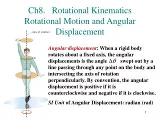
ezi Zi+1 ai Zi-1 bi Zi Oi-1 Oi+1 ri exi Xi+1 hi i i-1 Oi Xi qi ex(i-1) REVIEW OF C-B NOTATION • This notation is based on the homogeneous cylindrical coordinates and bryant angles transformations matrices and hence termed c-b notation. • The homogeneous transformation matrix is given by • Ti (i, hi, ri, i, i)=Tci(i, hi, ri) Tbi(i, i)
CYLINDRICAL COORDINATES Tc(, h, r)= Tr(Z, ) Tt(Z, h) Tt(X, r) = Tr(Z, ) represents rotation about Z-axis Tt(Z, h) represents translation h along Z-axis Tt(X, r) represents translation r along X-axis
BRYANT ANGLES CONVENTION Tb(, , ) = Tr(X, ) Tr(Y, ) Tr(Z, ) = Tr(X, ) represents rotation about X-axis Tr(Y, ) represents rotation about Y-axis Tr(Z, ) represents rotation about Z-axis
HOMOGENEOUS SHAPE MATRIX T(, h, r, , ) = Tc(, h, r) Tb(, , 0) = Y Z Y Z X h = l r = 0 = 90 = 0 l l Y X X Z h = 0 r = l = 90 = 0 Z Y X
ROBOKINE • Written in java and java3d. • Java used for generating the homogeneous matrices • Java3d for generating 3-dimensional features and simulations. • Contains 18 classes, 350+ methods and numerous variables • Advanced features include • Automatic C-B notation table generation (24 X 24 X 2) • Workspace generation (solid and wire frame modes) • Dynamic slice of the workspace in real time • Single slice of the workspace • Solving inverse kinematic problems • Trajectory planning
FEATURE 1 DISPLACEMENT ANALYSIS AND WORKSPACE GENERATION • Generate workspace profiles for even 3-dimensional robots and also for robots which does not have adjacent axes parallel or perpendicular to each other. • Can validate the generated profiles with the use of “Dials”. • Kinematic analysis consists of position or displacement, velocity and acceleration analyses. • The workspace / work volume of a robotic manipulator is defined as the set of all 3-dimensional points that can be accessed by the manipulator. • One of the design criteria for design of robots. • Study of robotic workspaces is important in arranging the associated flexible manufacturing cell of a robot and assessing its efficiency in a manufacturing line.
DISPLACEMENT ANALYSIS The general homogeneous characteristic matrix, ti, for different kinematic lower pairs are given by Ti = The position analysis of the end effector or manipulator can be obtained from this resultant matrix h given below H = Where D is direction cosine matrix and P is position vector and these specify the orientation and position respectively.
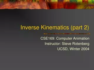
FEATURE 2 VISUALIZATION BASED INVERSE KINEMATICS SOLVER • A graphical, visualization based technique is developed to solve inverse kinematic problems without resorting to the numerical procedures. • Given the target point, finding the values of the joint parameters to reach that desired point. • The difficulty in solving inverse kinematic problems is because of its non-linear nature. the difficulties associated with this non-linearity are • Multiple to infinite solutions • No solutions because of divergence • The convergent set of solutions obtained may not be a desirable solution to the problem
FEATURE 3 VISUALIZATION BASED TRAJECTORY PLANNER • A visualization based trajectory planner is developed to accomplish this task. • Drastic reduction in time for planning trajectories and ease of use. • Obstacle avoidance. • Robots can be pre-programmed in either point-to-point mode or continuous path mode. • Point-to-point mode is used for tasks such as spot welding, inspection and moving parts. • Continuous path mode is used for tasks such as spray painting and arc welding.
ROBOKINE USER INPUTS NUMBER OF JOINTS AND MAXIMUM CO-ORDINATE VALUES OF SKETCHING USER INPUTS FOR GENERATING THE HOMOGENEOUS SHAPE MATRICES FOR EACH OF THE JOINTS DATA SAVED INTO AN OUTPUT FILE UNIMATE 2000 SPHERICAL ROBOT ALGORITHM GENERATES SHAPE MATRICES FROM C-B NOTATION TABLE, FOR EACH OF THE JOINTS IN THE CONFIGURATION UPJ ROBOT 2- SLICE OPTION 3- REAL TIME OPTION 1- PLOT OPTION EXIT
NUMERICAL EXAMPLES • CINCINNATI MILACRON T3 ROBOT • BENEDIX AA/CNC INDUSTRIAL ROBOT • UNIMATE 2000 SPHERICAL ROBOT • KR 60 P/2 ROBOT • UPJ ROBOT
CINCINNATI MILACRON T3 ROBOT (RRR/RRR) C-B NOTATION TABLE WORKSPACE INVERSE KINEMATICS
BENDIX AA/CNC INDUSTRIAL ROBOT (RRP/RRR) C-B NOTATION TABLE WORKSPACE INVERSE KINEMATICS
UNIMATE 2000 SPHERICAL ROBOT (SP/RRR) C-B NOTATION TABLE WORKSPACE INVERSE KINEMATICS
KR 60 P/2 (6R) C-B NOTATION TABLE WORKSPACE INVERSE KINEMATICS
UPJ ROBOT C-B NOTATION TABLE WORKSPACE INVERSE KINEMATICS
LIMITATIONS • The dials take in integer values • The orientations of the links have to be either horizontal and vertical while sketching the links at home position • Range of the input parameters of the joints should pass through zero or contain zero • If one of the joints in the configuration is helical other than the base then the workspace is not generated • Workspaces generated in certain cases may not be 100% accurate because of the following reasons • 1) Joints with no range of motion • 2) Algorithm considers maximum reach position when all the links are set to zero which may not be the case in certain configurations • Workspace generated is based on the projection of the profile on the sagittal plane
The results and plots generated can be saved nor printed • The inputs have to be provided each time the application is started • Software limitations • Hardware limitations FUTURE WORK • Velocity and acceleration spaces • Dynamic analysis • Closed chain and combined open and closed chain analyses