Download
1 / 8
140 likes | 507 Vues
Improvements in throughput in 802.11n.

E N D
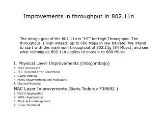
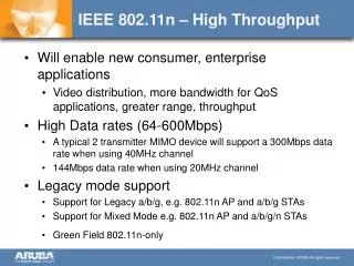
Improvements in throughput in 802.11n The design goal of the 802.11n is “HT” for High Throughput. The throughput is high indeed: up to 600 Mbps in raw bit-rate. We intend to start with the maximum throughput of 802.11g (54 Mbps), and see what techniques 802.11n applies to boost it to 600 Mbps including other improvements: I. Physical Layer Improvements (Bozhidar Zlatev F39703) 1. FEC (Forward Error Correction) 2. More subcarriers (OFDM overview) 3. Guard Interval and Windowing 4. Channel Bonding 5. MIMO (Beamforming and Multipath) II. MAC Layer Improvements (Boris Todorov F38692 ) 1. MSDU Aggregation 2. MPDU Aggregation 3. Block Acknowledgement 4. Lower Overhead
Low-density parity-check (LDPC) codes: class of linear block LDPC codes -> parity-check matrix contains only a few 1’s. Main advantage is performance which is very close to the capacity for a lot of different channels and linear time complex algorithms for decoding. Furthermore are they suited for implementations that make heavy use of parallelism. Improvement: ratio of data vs correction bits is 5/6. It was 3/4. Parity Check matrix Bipartite graph form
The trouble with traditional FDM is that the guard bands waste bandwidth and thus reduce capacity. To avoid wasting transmission capacity with unused guard bands, OFDM selects channels that overlap but do not interfere with each other. There is less severe intersymbol interference since the subcarriers do not contribute to the wave form, but there is possibility for intercarrier interference due to doppler effect. When one subcarrier is peaking the others are at zero amplitude
Intersymbol interference is caused in multipath environments when the beginning of a new symbol arrives at the receiver before the end of the last symbol is done. These two symbols arrive over two different paths. The “late” symbol that has not yet been completely received when the new symbol arrives traveled a longer path than the new symbol. However if guard time is “silent” it can destroy ortogonality due to delays. That is why each subcarrier signal is extended back through the preceding guard time: Transitions can be abrupt at symbol boundaries. Windowing is used to ramp up/down signal
When using the 40-MHz bonded channel, 802.11n takes advantage of the fact that each 20-MHz channel has a small amount of the channel that is reserved at the top and bottom, to reduce interference in those adjacent channels. When using 40-MHz channels, the top of the lower channel and the bottom of the upper channel don’t have to be reserved to avoid interference. These small parts of the channel can now be used to carry information. That is why we have 52 subcarriers for 20 Mhz channels and 108 for 40 Mhz channels.
For 802.11a and 802.11g, a symbol lasts 4 microseconds, including an 800 nanosecond guard interval each symbol carries up 216 data bits (depending on data rate). In addition, there are 72 error- correction bits sent in each symbol at 54 Mbps, for a total of 288 bits in the symbol. This means 6 bits (data + error correction). Each subcarrier uses 64 QAM (Quadrature Amplitude Modulation) but can also use QPSK or other modulation methods for different data rates. 802.11n continues to use OFDM and a 4-microsecond symbol, similar to 802.11a and 802.11g. However, 802.11n increases the number of subcarriers in each 20-MHz channel from 48 to 52. This marginally increases the data rate to a maximum of 65 Mbps, for a single-transmit radio. The maximum four transmitters can deliver 260 Mbps. However there is an option of shortening the guard interval to only 400 nanoseconds if the environment allows it (not great differences in multipaths) and we have 72, 44, 216,and 288 Mbps for a 20 MHz channel and 150, 300, 450, and 600 Mbps for a 40 MHz channel (40 Mhz channel has 108 subcarriers, 20 Mhz has 52).
MIMO uses some of the effects considered negative such as reflections and delays of the signal wave in order to achieve higher throughput. Transmit beamforming uses multiple antennae to send a stronger (higher SNR) signal to a single receiver, usually there have to be only a few reflective surfaces. Requires draft N devices since feedback from receiver is necessary to calculate the phaseshift. These sines cancel each other, when one peaks the other is at the bottom.
A MIMO radio sends multiple radio signals at the same time and takes advantage of multipath. Each of these signals is called a spatial stream. Each spatial stream is sent from its own antenna, using its own transmitter. Because there is some space between each of these antennae, each signal follows a slightly different path to the receiver. This is called spatial diversity. Each radio can also send a different data stream from the other radios. The receiver has multiple antennas as well, each with its own radio. Each of the receive radios independently decode the arriving signals. Then, each radio’s received signal is combined with the signals from the other receive radios. 2x2 multiplexing(two receivers 2 transmitters). 4x4 is the maximum possible. 3x3 and more lead to smaller gain improvements