Download
1 / 1
20 likes | 241 Vues
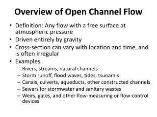
Simulation of Fluid Flow in the Deep Open Channel of the BMC Apparatus. = Deep Open Channel. Lana Sneath and Sandra Hernandez Biomedical Engineering Class of 2015, University of Cincinnati Faculty Mentor: Dr. Urmila Ghia , Mechanical Engineering. Introduction.

E N D
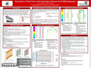
Simulation of Fluid Flow in the Deep Open Channel of the BMC Apparatus = Deep Open Channel Lana Sneath and Sandra Hernandez Biomedical Engineering Class of 2015, University of Cincinnati Faculty Mentor: Dr. UrmilaGhia, Mechanical Engineering Introduction Boundary Conditions: Calculating K and C2 Results: Porous Boundary Model Asbestos toxicity has been shown to vary with fiber length. To conduct larger scale studies on this effect, a fiber separator capable of filtering large batches of fibers based on length is needed. Fibers align with local shear stress vectors, therefore fibers will be filtered when the shear stress is parallel to the wire-mesh. This study evaluates the effectiveness of the Bauer McNett Classifier (BMC) as a fiber separator. To model a porous boundary in FLUENT, the values of the permeability (k), pressure-jump coefficient (C2), and the thickness of the porous boundary need to first be determined. For a 16 mesh, wire diameter = 0.0004572. Screen thickness is 2d, equal to 0.0009144. F and are standard coeficients for a 16 mesh [5] These values are entered into FLUENT to analyze the flow in the porous boundary model. Permeability (K): Pressure-Jump Coefficient (C2): = 7610.739 Porous wall Porous wall Solid wall Solid wall • Figure 8: X-velocity contours in top half of channel; plane at x= 0.2 m • Velocity contours bulge towards corners • Not-symmetric across the center of the channel • Highest velocity is in the center of the channel • Figure 9: X-vorticity contours in top half of channel; plane at x= 0.2 m • High vorticity at the free surface and near porous boundary • As previous case, vorticity is low at right side wall • Top corners are much more non-symmetrical about the angle bisector Figure 1. Side view of BMC apparatus Figure 2. Top view of elliptical tank in the BMC Methods and Materials Results: Solid Side Walls Model • Goal: Numerically study the fluid flow in a deep open channel • Objectives: • a) Learn the fundamentals of fluid dynamics. • b) Learn the fundamentals of solving fluid dynamic problems numerically. • c) Simulate and study the flow in the open channel of the BMC apparatus, modeling the screen as a solid wall boundary (i) • d) Model the screen as a porous boundary (ii) • e) Determine the orientation of shear stress vector on screen boundary for both (i) and (ii) • Materials: • Computational Fluid Dynamic (CFD) tools FLUENT and Gambit • Steps in Methodology: • Define channel geometry • Set up channel geometry in Gambit and generate a computational grid • Enter boundary conditions and obtain flow solutions • Solid Wall Model • Porous Boundary Model • Compute shear stress on flow solutions Discussion • These findings indicate that the total shear stress value is greatest at the inlet, and quickly drops down as the x-position increases. • In the solid-wall model, the highest out-plane angle where the screen lies in the actual BMC channel is 8 degrees, which is primarily tangential to the wall. • The shear stress magnitude in the porous boundary model is expected to be slightly greater. The difference is expected to be determinedin future work. • Flow through the screen is expected to be small, hence the contribution of the porous boundary to the off plane shear stress angle is expected to be small • Future work of this study: • Analyze the shear stress distribution of the porous boundary model • Understand the behavior of fluid flow in the porous boundary model • Figure 5: X-velocity contours in top half of channel; plane at x= 0.2 m • Velocity contours bulge towards corners • Symmetric across the center of the channel • Highest velocity is in the center of the channel • Figure 6: X-vorticity contours in top half of; plane at x= 0.2m • Top corners are non-symmetrical about the angle bisector • High vorticity at the free surface • High vorticity is attributed to the free surface being modeled as a free-slip wall Acknowledgements We would like to thank Dr. Ghiafor being an excellent faculty mentor and taking the time to make sure we fully understood the concepts behind our research. We would also like to thanks our sponsor, the National Science Foundation , Grant ID No.: DUE-0756921 Solid Wall Model Porous Boundary Model Figure 4. Boundary Conditions References Figure 3. Channel Geometry in Gambit Jana, C. (2011), “Numerical Study of Three-Dimensional Flow Through a Deep Open Channel-Including a Wire-Mesh Segment on One Side Wall.” M.S. Mechanical Engineering Thesis, University of Cincinnati. White, F. M. (2003) “ Fluid Mechanics”, McGraw-Hill, 5th Edition. Fluent 6.3 User’s Guide. Gambit 2.4 User’s Guide. Tamayol, A., Wong, K. W., Bahrami, M. (2012) “Effects of microstructure on flow properties of fibrous porous media at moderate Reynolds number”, American Physical Society, Physical Review E 85. Free-Slip Wall, v=0, du/dy=0, dw/dy=0 No-Slip Wall, u = v = w = 0 Table 1. Distribution of grid points and smallest spacing near boundaries Inlet, u = u(y,z), v = w =0 Figure 7: Total Shear Stress Magnitude (primary y-axis) and off plane angle (secondary y-axis) along the Z-Wall; line at y= 0.1 m (mid-plane), z= 0.02 m Outlet, pstat = 0 Porous-Jump, K = 9.6e-10, C2=7610.7 1/m, screen thickness = 9e-4 m; Values correspond to 16 a mesh [5]