In-Situ Testing of FPGA Devices in Space Environment for SEU Mitigation
This research focuses on developing an experimentation platform for in-situ testing of FPGA devices in a low Earth orbit (LEO) environment, specifically utilizing 9 XQVR1000 BG560 devices. Conducted by Los Alamos National Laboratory, the study aims to evaluate the performance of SRAM-based FPGAs in mitigating single event upsets (SEUs) during space missions. The platform supports reconfigurable computing, enabling new configurations post-launch and investigating fault tolerance and system resilience for on-orbit applications.

In-Situ Testing of FPGA Devices in Space Environment for SEU Mitigation
E N D
Presentation Transcript
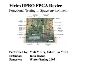
Testing FPGA devices in Space Environment Prasanna Sundararajan, Bob Patrie, Robert Wells Xilinx Inc Michael Caffrey, Paul Graham Los Alamos National Laboratory
Cibola Flight System • Experimentation platform for FPGA in-situ testing • Developed at Los Alamos Laboratory • LEO orbit RF remote sensing experimental payload • Demonstrates the use of reconfigurable computing on-orbits • Uses 9 XQVR1000 BG560 devices • Used to study system level SEU mitigation perfomances
Cibola Flight System RCC 3 Virtex FPGAs with Memory dcard RCC 3 Virtex FPGAs with Memory dcard RCC 3 Virtex FPGAs with Memory dcard Analog Tuner 2 Channel 12bit ADC@100MHz 2 Channels 20 - 500 MHz RF 2 Channels 55 - 95 MHz IF Results to ground 2 Channel TTL 12 bits@100MHz 2 Channel TTL 32 bits@50MHz • New configurations deployable after launch • Slow ~15 min • Device bitstream readback capability allows: • On orbit readback data analysis (fast < 1 s) • Downloading readback data to earth (fast < 1 min)
RCC Functional Diagram Local SDRAM 3 separate banks each 32 x 8M Processor A FPGA 36 data 3 control Input only: Two 12 bit samples + ECC @50MHz 36 data 3 control Processor B FPGA Local SDRAM 3 separate banks each 32 x 8M 32 data FPDP Buffer 36 data 3 control Input / Output by assembly 32 data Processor C FPGA FPDP Buffer Local SDRAM 3 separate banks each 32 x 8M SEU CRC XQVR configuration Microprocessor interface Actel controller Backplane Interface ASCM
RCC System • Bandwidth • FPDP 200 Mbytes/sec each port (32 bitsx50MHz) • Ring bus up to 104 MHz • Memory 32 bits@52 MHz in 3 independent banks • Each bank 2 parts deep so refresh does not reduce bandwidth, data at every clock • Microprocessor interface ~3 Mbytes/sec • Configuration File Sharing • Bitfiles and designs can be shared amoung any FPGAs as pinouts identical on all XQVR
RCC System Level Test • Built in test will fly • Two test configurations for 9 XQVRs • Tests system from ADC through 3 RCC modules • Tests for open, short, ground bounce and crosstalk • Fault Isolation via verifier ID and failure data pattern • Bitstream SEUs • All XQVR bitstreams readback every 180ms • CRC computed on individual frames and compared with codebook, generated on the ground • Microprocessors can inject SEUs into XQVR1K to observe upset consequence and test system response
RCC System Level Test Verify Test Pattern Generate Test Pattern Local SDRAM 3 separate banks each 32 x 8M 36 data 3 control x3 Local SDRAM 3 separate banks each 32 x 8M 36 data 3 control 32 data FPDP x3 Buffer 36 data 3 control 32 data Local SDRAM 3 separate banks each 32 x 8M FPDP x3 Buffer SEU CRC Processor configuration Actel controller Backplane Interface ASCM Test Pattern 0xFF..FE 0x00..00 0xFF..FD 0x00..00 0xFF..FB 0x00..00 0xFF..F7 System test do not test XQVR Silicon
Motivation • SRAM FPGAs offer many features to on-orbit systems: • Processing capacity • Time to market • Cost and Reconfigurability • SRAM FPGAs conducive to in-situ system testing • Lifetime of the SRAM-based FPGA system can be extended • Fault detection and Isolation • Reconfigure around faults
Objectives • Perform In-situ testing of FPGAs on Cibola Flight after depolyment • Enable on-orbit FPGA systems to degrade gracefully • Exploit reconfiguration to extend system lifetime • Understand issues in degradation of systems utilizing SRAM-based FPGAs
In-situ Silicon Testing • Logic testing using Xilinx Reconfigurable Self Test (XRST) • Three bit streams are applied to cover CLB and BRAM: • 100% - LUT RAM & flip flops • 100% - X,Y,XQ,YQ outputs • 100% - F1..F4, G1..G4, BX,BY,CE,SR,CLK inputs • Coverage of additional resources requires additional bitstreams (Carry logic, TBUF, I/O) • BRAM Memory locations • Initial study to conduct wire testing performed
FRCERR Instance 1 Instance 1 GO CONTROL CONFIG INTERFACE Instance N Instance N Drives each Instance CRC XRST Block Diagram CRC
XRST Logic Test • Configure a portion of an FPGA device to perform as a functional tester to: • Apply stimulus • Measure responses • Recorde results • Interchange the portions to be tested with the tester mechanism to provide maximize coverage • Application of the process can be independent of the user system
From previous RAMLFSR From previous MSBCOMP RAMLFSR RAMLFSR RAMLFSR RAMLFSR MSBCOMP MSBCOMP To next MSBCOMP input - XRST Instance Block Diagram From CONTROL FRCERR to 1st RAMLFSR only • A 0 is clocked onto the MSBCOMP chain when the MSBOUT of two or more RAMLFSR’s disagree or when • an error occurs upstream • As CLK edges appear, the 0 is • propagated to the end of the chain • A zeros catcher latches any • 0 transition at the end of the chain • to indicate an error ( some MSBOUT’s differ ) Instance 1 Instance 0 To next MSBCOMP One RAMLFSR output goes to CRC
Test Pattern Floorplans Control RAMLFSR Other BLK RAM #1 #2 #3 Cover Even Rows Cover Odd Rows Cover Control Area + Block RAM Control Area not tested - 28 CLB’s
In-situ Wire Testing • Complete wire testing requires more patterns than the logic testing • Initial study was conducted to estimate the number of configurations required to test “Singles” wire type • It was assumed that the configurations to test the wire would be uploaded from the ground station
Wire Testing • Testing Singles wire type • Total 96 singles/CLB with 24 in each direction • 20 of 24 singles have OMUX associated with them • Initial tests cover 80 single wires/CLB • 4 singles/CLB can be tested in parallel in one single session • One Test Session => One configuration, 2 readback • Total of 20 configuration and 40 readback would be needed
4 LUT Buffer/ Inverter 4 LUT Buffer/ Inverter Wire Test O M U X FF Singles Wire Under Test
Wire Test Session • Configure the test data • Column 0 as buffer and other columns as inverters • Connect the CLB with the wire under test • Init all FF to ZERO • Step Clock 1 • Send Readback Command • Readback entire CLB data and check for SA-1 • Step Clock 1 • Send Readback Command • Readback entire CLB data and check for SA-0 • Iterate above steps to test other singles
Compression of Test Patterns • To reduce the time required to transport the data, test patterns were compressed • GZIP compression utility from Java development kit was used
Summary & Future Work • FPGAs are uniquely suited for in-situ testing after deployment • A novel self-test mechanism to test the logic resources was developed • Initial study to test the wire types was conducted • Graceful system degradation possible by fault detection and isolation • Future work would involve design specific routing testing to maximize coverage