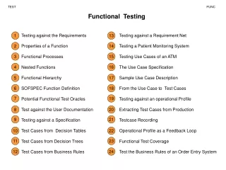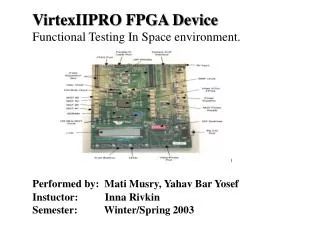
VirtexIIPRO FPGA Device Functional Testing In Space environment.
420 likes | 568 Vues
VirtexIIPRO FPGA Device Functional Testing In Space environment. Performed by: Mati Musry, Yahav Bar Yosef. Instuctor: Inna Rivkin Semester: Winter/Spring 2003. Contents System Overview FPGA specific testing PPC specific testing

VirtexIIPRO FPGA Device Functional Testing In Space environment.
E N D
Presentation Transcript
VirtexIIPRO FPGA Device Functional Testing In Space environment. Performed by: Mati Musry,Yahav Bar Yosef Instuctor: Inna Rivkin Semester: Winter/Spring 2003
Contents • System Overview • FPGA specific testing • PPC specific testing • Integrated test • Application tests • System configuration • User Interface
SUMMARY • TEST PERFORMED: • The tests that were performed are classified into 4. • Functional testing of internal modules not including PPC405. • Functional testing of PPC405 independent internal modules. • Integrated test • Application testing. • Functional testing of internal modules not including PPC405 performed are: • Live Test, Verify Test, IOB test, CLB memory test, CLB flip-flops test, CLB logic test, Block RAM test, • Fast Multipliers test, DCM test, MGT test. • Functional testing of PPC405 independent internal modules performed are: • Registers, MMU, Cache (data & instructions), CPU, On chip memory, Timer resources (PIT), • Exception handling logic, Peripheral test. • Integrated testing: • micro-controller application. • Application testingperformed are: • I/o application,MGT application
SYSTEM OVERVIEW: User Interface Led1 Led2 Led3 Led4 Dip switch 1
DUT Design for modules not part of embedded PPC DUT Design Overview: ICON (Integrated Controller) core provides a communication path between the host computer via a JTAG download cable and the target VirtexIIpro FPGA. ILA (Integrated Logic Analyzer) core is a customizable logic analyzer core that can be used to monitor any internal signal of the design under test and pass this data back to the host computer via the ICON core.
DUT Design Description DUT Design Algorithm: 1.Perform memory test on Bram configured for capturing. 2. Perform test per given MUT.(capture Input&output per given MUT design)
IOB Test MUT MCT
XMD – PPC interface ppcconnect
XMD flow TCL script XMD GDB PPC
Registers test • performs a check that the processor’s GPRS (general purpose registers) are working correctlly – that is, a data that is stored in them stays stable and can be read and verified. • each test writes a value to all the writable registers and then perform a read of all the registers. The values written are 0xffffffff, 0xaaaaaaaa and 0x55555555
Cache test • Tests the Instruction cache/tag and the Data cache/tag • map Caches to unused memory addresses and then from the debugger access it as memory addresses • The test itself is a memory test, and consists of writing values to the memory and then reading it, comparing with the expected results file. The values are as mentioned in the registers test
Memory test • The memory test consists of several values written to the PPC connected memory, and then reading those values, comparing with our expected results of the golden file • We use the XMD command “memory write” mwr $i 0xffffffff to write the value 0xffffffff for example, to the address that $i holds ($i is our iterator), and then we use the command “memory read” mrd $i 1 to read the values. • The results are written to a file, and compared to a golden file which holds our expected values.
MMU test • In the MMU test, we actually test the TLB, and we do it using the options given to the ppcconnect command, mentioned in the Cache test. The algorithm is the one used in memory/cache tests.
Integrated test micro-controller application Leds FPGA MODULE Lcd Hyper Terminal
First design Creating MHS file (XPS) Platgen – HW platform created Create MSS file (XPS) Libgen – SW platform created Create C code (Editor) Program & Debug (XMD) Compile – elf file created Program & Run application (Impact) Software flow for PPC test
Application test i/o application This application is designed to check the I/O peripherals of the board using the PPC. A design that shows that the PPC communicates correctly with the environment MGT application In this application we perform packet sending in serial Loop back via the MGT, the test is controlled by PPC Exceptions/Timers test application In this application we test the timers and the exception mechanisms of the processor
SYSTEM ALGORITHM Initial Assumption: FPGA is functionally valid before radiation. Test Request • System configure DUT. • System Activates Test • System outputs Golden file System-configure mode Golden File Test Request • System configure DUT • System Activates Test • System compare result with Golden file • System outputs result System-run mode Output
System Limitation • No real time memory allocation if captured memory is faulted • Setting new captured memory requires new synthesis • Capture memory setting causes decrease in mapping %
A Look To the future… • 3 kind of systems (memory manger, Mgt, readback) • Readback (more then config mem) is the best solution but requires additional hardware. • Mgt requires another board and possibly memory space for left over • Mem man are: ppc, chipscope, sram controller • PPC is best solution most convieniant ,easy solution for • Realocation, can control capture, no additional logic • An optimal system is a mixture of all 3.