Introduction to Flexible Electronics I
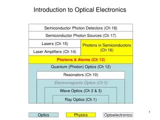
Introduction to Flexible Electronics I. Michael Thompson – MS&E Cornell University LIFE ERC Discussions February 24, 2007. Integrated Electronics. Applications for Flexible Electronics. Display. Memory. Smart Card. Optical Network. HDI. Imaging. Solid State Lighting. Gen 8.


Introduction to Flexible Electronics I
E N D
Presentation Transcript
Introduction to Flexible Electronics I Michael Thompson – MS&E Cornell University LIFE ERC Discussions February 24, 2007
Integrated Electronics Applications for Flexible Electronics Display Memory Smart Card Optical Network HDI Imaging Solid State Lighting
Gen 8 Gen 7 Gen 6 Gen 5 Gen 3-4 Large area manufacturing – pioneered by glass AMLCD 100 MM ft2 shipped in 2002
Al Al Barrier SiO2 Substrate (Plastic or otherwise) Key elements in the thin film TFT • Passivation or barrier SiO2 layer • Structural and electrical limiter • Thermal expansion mismatch • Limits high-T processes even on high-T compatible substrates • Channel and Source/Drain semiconductor • High performance by laser crystallization • Gate dielectric • Coupled with channel properties determines transconductance Gate metal (self-aligned?) Gate dielectric Source/drain (doped)
Meanings of flexible electronics • Flexible is a poor moniker for a broad set of properties • Bendable • Actively deformed during end-use • Range from small infrequent deformation (cell phone) • Continuous large scale deformation (fabric-based electronics) • Shape tolerant • Deformed to match application (windshield) • Rollable format (volume sensors) • Conformal electronics • Fabricated on/to non-standard shapes (spherical detectors) • Stretchable electronics • Large scale reversible deformation (bandages) • Large area electronics • Sparse active components (sensor area enhancement) • Dense active components (displays) • Low cost electronics • Disposable / single use • Large volume, low value (RFID)
Flexible glass substrates • Flexible glass substrates • Durable for military applications • Effective barrier to air and moisture for OLEDs • Corning has patented hermetic sealing method • Low-cost manufacturing process • Researching polymer coatings
Technology Goals for poly-Si TFTs • Low temperature process • Compatibility with transparent polymeric substrates for display applications • Maximum static process temperatures of ~150oC • High performance devices • Amorphous Si and organic TFT’s have inadequate current (mobility <10 cm2/V-s) • Poly-Si or near single crystal (200 cm2/V-s) required • Critical front-end processing (FEP) challenges • Crystallization of poly-Si • Dopant activation • Low temperature gate dielectric • Critical back-end processing (BEP) challenges • Contact sintering • Hydrogenation • Pixel module integration
Alternative TFT Technologies • Low / moderate performance on plastic • Amorphous Si TFTs • Uniformity • Developed Technology • Polymer / Small molecule organic TFTs • Potential low-cost processing / printed technology • Substrate selection • Stainless steel foils • Ultra-thin glass • Transfer technologies • SUFTLA thin-film transfer • Wafer scale exfoliation • Thin-film single-crystal platelets • Other crystal techniques • Microcrystalline deposition (performance?)
Application driven requirements: Mobility • Electron/hole mobility: transit speed across device • Gate capacitance (dielectric thickness): carrier density in channel • Ultimate technology speed depends on mobility, gate capacitance, and uniformity (to utilize both)
Roll-to-Roll Manufacturing Thin Film Deposition & Laser Processing Photolithography Lamp Supply Roll Take-Up Roll Photomask Transfer Rolls Cooling Drum SiO2 Laser Supply Roll Take-Up Roll Silicon Metal Transfer Rolls Take-Up Roll Supply Roll Wet Chemical Etching & Cleaning Etch Bath
Roll-to-roll Manufacturability Studies • Initial development on deposition and laser processing • Ongoing discussions with lithography tool manufacturers • Characterization of defect generation in roll-to-roll web handling
Manufacturing Strategy Roll to Roll Cost savings Plate to Plate Cap Ex est.: 1 : 4 ratio Mfg Cost est.: 1 : 3 ratio Early applications Pilot Production Time line
Kodak/Cornell OLED AM display Pixel Layout OLED Display as finished at Kodak Active Matrix: Two displays per wafer, fabricated at Cornell CNF D. Ast
Flex Stainless Steel (E-Ink) • 1.6” diagonal • 80 ppi (100x80) • 0.30mm thickness
Ability to fabricate high purity GaN particles From ~10 mm size into 30 nm size Particles can be spun coated (as shown) Rare earth doping all colors (red shown) Process temperatures for device fabrication are compatible with flexible substrates (Spencer) GaN particles for illumination or TFT applications
Low cost, versatile method for large area printing Needs new inks, new processes, new device designs Ideal research area to complement CAMM Cornell expertise in ink design, nanoparticle processing (Ober, Wiesner, Thompson) Ink Jet Patterning
deposit compliance layer and thermal isolation oxide 2. deposit a-Si 3. crystallize a-Si (excimer laser) 4. deposit gate oxide 5. deposit gate electrode 6. pattern gate (mask # 1) dope source/drain Implant + laser anneal In-situ doping + laser anneal 8. pattern Si device regions (mask # 2) 9. deposit contact isolation oxide 10. pattern & etch contacts (mask # 3) deposit and pattern metal (mask # 4) Low-T ITO deposition and patterning 5 4 2,3 1 Metal or poly-Si Gate SiO2 poly-Si Compliance & Thermal Barrier doped Plastic Substrate polysilicon 6 7,8 M n+ Si Si n+ Si Barriers doped Plastic Substrate polysilicon 150oC TFT on Plastic Process Steps 12 ITO SiO2 11 9,10 M Al Al Si SiO2 SiO2 n+ Si n+ Si Barriers doped Plastic Substrate polysilicon
GATE SOURCE DRAIN SiO2 G Al Al Si SiO2 SiO2 SiO2 doped Plastic Substrate polysilicon TFT Performance Metrics • Mobility: high current capability (OLED display brightness and fast driver circuits) • Threshold voltage control • Sub-threshold slope (steep on-off transition) • Device uniformity Drain-SourceCurrent(to OLED) Mobility Threshold Voltage Gate Voltage log Drain-SourceCurrent Sub-thresholdSlope(volts/decade) Gate Voltage
-3 160.0 10 -4 140.0 10 VG = 20.0V µn = 44 cm2/V-sec -5 120.0 10 S = 1.7 V/decade -6 100.0 10 (Amps) (µA) VG = 17.5V -7 80.0 10 DS I VDS = 10.0V DS I -8 60.0 10 VG = 15.0V VDS = 1.0V -9 40.0 10 VG = 12.5V -10 20.0 10 -11 0.0 10 -10 0 10 20 30 40 0 5 10 15 20 V (Volts) V (Volts) DS GS W/L = 100/50 µm Typical TFT on Plastic Performance • 100ºC maximum process temperature
NMOS TFT performance: Mobility > 250 cm2/V-s Threshold voltage ~ 5 V Sub-threshold swing:~ 0.5 V / decade PMOS TFT performance: Mobility ~ 125 cm2/V-s Threshold ~ -5.5 V Sub-threshold swing~ 1.2 V / decade W/L = 20/10 “High-performance” TFT results
Active Matrix TFT with integrated OLED • TFT provides correct current level (~10 A) to OLED for desired intensity. Plastic Substrate Passivation Layer SiO2 Current Flow SiO2 Cathode SiO2 SiO2 OLED ITO Al Al Al SiO2 Al SiO2 Barrier SiO2 Plastic Substrate Light!
Summary • Key requirements for flexible driven • Large area sparse • Moderate density but absolute flexibility • Conformable requirements • Bio/environmental compatibility precludes Si • Can’t be done with existing Si electronics • Particularly packaging