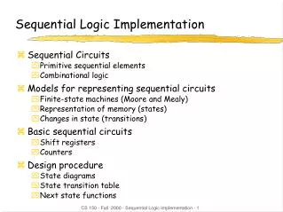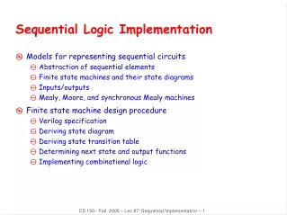
Sequential Implementation of Y86 Processor
Sequential Implementation of Y86 Processor. Y86 instruction set. Function Codes for Y86 instructions. Y86 Register Identifier. 8 for No Register. SEQ implementation of OP1, rrmovl , irmovl instrucions. SEQ implementation of rmmovl and mrmovl instructions.

Sequential Implementation of Y86 Processor
E N D
Presentation Transcript
Y86 Register Identifier 8 for No Register
SEQ Hardware Structure • Processing is performed by different hardware units • Control logic blocks constitute a control unit. • Each implementation stage require some combinational or sequential H/W components to perform the task in that stage. • E.g Execute stage require ALU to perform arithmetic and logic operation. • Purpose of control logic boxes: • These are used to map the computation into h/w. • These will generate control signals and transfer data accordingly from one h/w unit to another.
Following are the SEQ H/W diagram conventions • Light Blue boxes: • These boxes shows h/w units in different stages • Control Logic Box: • Are shown by gray rounded boxes • Names of the wires are shown as white round boxes • 32-bit data passed through medium lines • Byte (8-bit) or any narrow data is passed through thin lines in diagram. These are bundle of 4 or 8 wires to represent 4 or 8 bit data. • Single bit connections are shown as dotted lines
SEQ Implementation • Consist of • Combinational logic • Two forms of memory devices • Clocked Registers • PC, CC (both required read and write operations) • Random Access Memory • Register file • Data Memory • Instruction memory • This memory is treated as combinational circuit since only read operation is done on it. • Read/write operation needs trigger of clock cycle signal (both required read and write operations)
SEQ Implementation in different stages • Fetch Stage • Instruction memory h/w unit • Split unit interprets first byte into icode and fcode • Generates three controls signals instr_valid, need_regids, need_valC
SEQ PC update Stage • If icode = CALL instrn • valC will have new PC • If icode = any jump instrn • valC will have new PC • If icode = ret instrn • valM will have new PC • If other than the above instrn is executed • valP will have new PC
SEQ+ implementation of Y86(Rearranging the computation stages) • Limitation of Y86 • It is too slow • Clock runs slowly so that signals can propagate through all of the stages within the single cycle. • This way of implementation does not make very good use of h/w units since at a time only one unit is active for sfarction of time of the total clock cycle. • Improvement to this is another implementation which is an extension to SEQ implementation called SEQ+. • The last stage (i.e PC update stage) comes at the beginning of the clock cycle.