Download
1 / 13
130 likes | 324 Vues
Why are you here? Ans: To provide feedback and information on how to verify that a design is truly flight worthy. Ans: To provide feedback on you convections about quality. Ans: To review how we validate performance or design quality now. Why am I here? Ans: To gather your feedback

E N D
Why are you here? Ans: To provide feedback and information on how to verify that a design is truly flight worthy. Ans: To provide feedback on you convections about quality. Ans: To review how we validate performance or design quality now. Why am I here? Ans: To gather your feedback Ans: To formulate concepts which will expand our understand of quality Ans: To propose and challenge you with some “new” or “old” ideas. Ans: To determine if there is a clear consensus
Other questions we should address? General Questions 1.) Why do we need to do WCA? 2.) How do you evaluate the quality of a design? 3.) When do we do EVA versus Monte Carlo, Sensitivity, RSS, etc? 4.) How many samples is enough? 5.) Does parameter distribution matter? 6.) Does seed number matter? 7.) Why do sensitivity analysis? 8.) When do we say that the design is “good enough”?
Do we have all the info we need? Background I wrote a paper for SYS611 last year entitled “Risk Assessment of a LM117 Voltage Regulator Circuit Design Using Crystal Ball and Minitab (Part 1)” I would like to write Part 2 of the paper which will focus on conventional circuit analysis of the same circuit. Design Requirements A 5VDC regulated voltage is required which can regulate +9VDC to +5VDC ±2.5%. To verify that the design will meet the requirements a risk assessment (worst case analysis) must be performed to demonstrate performance. The design must regulate to the desired voltage after five years of use and in an environment of -25°C to +75°C. The output load will be 100mA and the input voltage will be 9VDC. The design will use standard available parts and no tailoring will be allowed.
Are we happy with the design? Initial Design – Nominal Performance The 5VDC regulator circuit will be designed using equation 1 which describes how the circuit shown in Figure 1 functions. The resistors that will be used are M55342 type surface mount resistors which have a ±1% tolerance and have been used in other designs. Equation 1 Figure 1 Table 1 - Initial Design
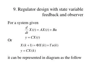
Do we meet the requirements? Supplemental Part 1 results 5V±2.5% = 4.875V to 5.125V All part distributions are Gaussian All part distributions are Flat
How do you get a good model? Ok, lets use PSPICE and see what we get. To use PSPICE you will need to overcome some tool and model limitations *------------------------------------------------------------------------ *** Voltage regulators (positive/adjustable) * * LM117 voltage regulator "macromodel" subcircuit * created using Parts release 5.3 on 04/08/93 at 11:33 * modified 2/26/07 by AGBell (ITT SSD) * * Vref has 4% tolerance * Iadj has a 100% tolerance * * connections: input * | adjustment pin * | | output * | | | .SUBCKT LM117AGB IN ADJ OUT * * POSITIVE ADJUSTABLE VOLTAGE REGULATOR * JADJ IN ADJ ADJ JADJMOD ;ADJUSTMENT PIN CURRENT *VREF 4 ADJ 1.25 E1 4 ADJ 40 0 1 IREF 0 40 1.25e-3 RREF 0 40 RMOD 1e3 DBK IN 13 DMOD * * ZERO OF RIPPLE REJECTION * CBC 13 15 8e-010 RBC 15 5 1000 * QPASS 13 5 OUT QPASSMOD RB1 7 6 1 RB2 6 5 128.3 * * CURRENT LIMITING * DSC 6 11 DMOD ESC 11 OUT VALUE {5.646-0.1125*V(6,5)*V(13,5)} * * FOLDBACK CURRENT * DFB 6 12 DMOD EFB 12 OUT VALUE {7.886-0.3727*V(13,5)+0.005097*V(13,5)*V(13,5) + -0.02*V(13,5)*V(6,5)} * EB 7 OUT 8 OUT 7.691 * * ZERO OF OUTPUT IMPEDANCE * RP 9 8 100 CPZ 10 OUT 3.979e-006 * DPU 10 OUT DMOD ;POWER-UP CLAMPLING DIODE RZ 8 10 0.1 EP 9 OUT 4 OUT 100 RI OUT 4 100MEG * .MODEL QPASSMOD NPN (IS=30F BF=50 VAF=8.891 NF=2.612) .MODEL JADJMOD NJF (BETA=50e-006 DEV=100% VTO=-1) .MODEL DMOD D (IS=30F N=2.612) .MODEL RMOD RES (R=1 DEV=4%) .ENDS
Does this look ok? This appears to agree with the Crystal Ball simulation but we have used Uniform distributions which should widen the spread.
Something is wrong? This appears not to agree with the Crystal Ball simulation. The spread is much wider than the Uniform… PSPICE has a problem with the interpretation of Gaussian and Cadence is working on it.
Model looks like it has lots of bells and whistles. Ok, lets use AWB and see what we get. Do we understand the model template? Device name: LM117AGB _____________________________________________________ Device Information: Device Placement: /LM117AGB Device Type: Adjustable Positive Regulator Body: /appmnt/prod/ECAD/cadence/cadence_psd_14.1/share/library/bodies/reg_adjust/sym_1/symbol.css SimName: SimLib: Parameter Information: --------------------- Reference Voltage (VR): 1.25 (4 %; 4 %; gauss0.4) V 1st TempCo of VR (TC1VR): -15 u ( ; ; ) /C 2nd TempCo of VR (TC2VR): -0.76 u ( ; ; ) /C^2 Line Regulation (LINREG): .01 ( ; ; ) %/V Load Regulation (LDREG): .1/1.5 ( ; ; ) %/A Quiescent Current (IB): 50 u (50 u; 50 u; gauss0.4) A Minimum Dropout Voltage (VDMIN): 1.5 ( ; ; ) V Dropout Voltage at IVD1 (VD1): 2.25 ( ; ; ) V Current for Dropout (IVD1): 1.5 ( ; ; ) A 1st TempCo of Dropout Voltage (TC1VD): -1179 u ( ; ; ) /C 2nd TempCo of Dropout Voltage (TC2VD): 7.9 u ( ; ; ) /C^2 Maximum Current (IMAX): 2.3 ( ; ; ) A Maximum VI-VO for max current (VMAIP): 11 ( ; ; ) V Linear slope of current limit (M1ILIM): -128 m ( ; ; ) A/V Quadratic slope of current limit (M2ILIM): 2.2 m ( ; ; ) A/V^2 1st TempCo of current limit (TC1IMAX): 0 ( ; ; ) /C 2nd TempCo of current limit (TC2IMAX): 0 ( ; ; ) /C^2 Timing Resistor (RT): .5 k ( ; ; ) Ohm Timing Capacitor (CT): 800 p ( ; ; ) Farad Max input-output voltage (VINMAX ): 40 ( ; ; ) V Max junction temp (TJ): 150 ( ; ; ) C J-C thermal resistance (RJC): 2.3 ( ; ; ) C/W C-A thermal resistance (RCA): 38 ( ; ; ) C/W Reference Voltage (VR): 1.25 (4 %; 4 %; FLAT) V Quiescent Current (IB): 50 u (50 u; 50 u; FLAT) A
Have we taken enough samples? This appears to agree with the Crystal Ball simulation but we have used Uniform distributions which should widen the spread.
We have good results but the tool is obsolete! This also appears to agree with the Crystal Ball simulation. However, AWB is no longer supported.
We have bad results, now what? Lets try the Advance Analysis in PSPICE. Results are not correct. Not all tolerances are accounted for. Cadence is working on it …
We are not done. The tools look like they have issues that need to be solved. We can’t trust the models. We have not answered our “general questions” yet. Not only do models need to be validated but maybe the tools as well.