Download

1 / 15
150 likes | 344 Vues
Ronald Harley Georgia Institute of Technology ECS-0231632 ECS-0080764. Kumar Venayagamoorthy University of Missouri-Rolla. Approximate Dynamic Programming and Reinforcement Learning for Nonlinear Optimal Control of Power Systems. November 4, 2003.

E N D
Ronald Harley Georgia Institute of Technology ECS-0231632 ECS-0080764 Kumar Venayagamoorthy University of Missouri-Rolla Approximate Dynamic Programming and Reinforcement Learning for Nonlinear Optimal Control of Power Systems November 4, 2003
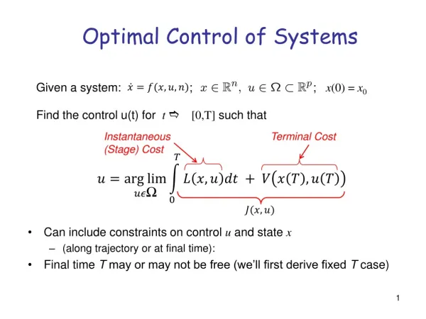
Adaptive Critic Design: Nonlinear Optimal Control Model Network Utility Plant (Identifier) U Informaton Function ( ) : To learn the dynamics of plant Optimal cost-to-go J function ( ) Critic Networks : To minimize the value (of derivatives) Plant J of with respect to the states Control Derivatives via BP Action Network : To find optimal control Model Network u Reinforcement Learning
Simulation Results 100ms SC at PCC, Line Voltage , Generator Terminal Voltage
Optimal control for FACTS devicesInternal control forstatic series synchronous compensator (SSSC) The simplified schematic of the SSSC (160 MVA, 15KV VL-L)
PI Based internal controller (CONVC) for the SSSC Publication: N.G. Hingorani and L. Gyugyi, “Understanding FACTS-Concepts and Technology of Flexible AC Transmission Systems”, IEEE Press, New York, 2000. Optimal control for FACTS devicesInternal control forSSSC (CONVC)
Rotor angle Optimal control for FACTS devicesCase study: 100 ms three phase short circuit test at receiving-end (infinite-bus)
Optimal control for FACTS devicesExternal control forseries capacitive reactance compensator (SCRC) Schematic single-line diagram showing an SCRC with external controller (160 MVA, 15KV VL-L)
v v r s Line #1 x r e1 v i e1 Turbine- c s Line #2 Governor x r e2 e2 Synchronous Inf. bus AVR - Generator Voltage Exciter * X Source C Inverter GTO D w + DHP based + Internal Control S external controller X + D of SCRC X C C (DHPEC) V dc SCRC Optimal control for FACTS devicesDHP based external controller (DHPEC) Schematic single-line diagram showing the DHP based external controller (DHPEC)
Speed deviation Optimal control for FACTS devicesCase study: Step changes X*C [pu]
Application in Multi-Machine power system Large-scale multi-machine power system
Governor 1 2 Vr UPFC Synch Generator V1 V2 Pref Turbine Z1 Z1 R2, L2 R1, L1 Pout, Qout Infinite Bus Series Inverter Shunt Inverter Exciter Vdc - V1ref AVR + Q ref V1 Shunt Inverter Control Series Inverter Control V1ref Qerr Verr Qinj Vdcerr Perr Vdc epd Neurocontroller Pinj Vdc ed Q Neurocontroller Vdcref V Neuroidentifier epq eq Pref Neuroidentifier P A UPFC in the POWER SYSTEM
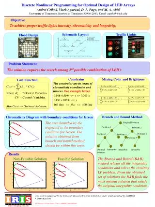
250 250 200 200 ) ) 150 150 ° ° 100 100 Load Angle( Load Angle( 50 50 0 0 UPFC UPFC NC PI PI PI - - 50 50 1.1 1.1 5 5 6 6 7 7 8 8 9 9 10 10 11 11 Time (sec) Time (sec) 1.08 1.08 1.06 1.06 Speed (Pu) 1.04 1.04 Speed (pu) 1.02 1.02 1 1 0.98 0.98 NC UPFC UPFC PI PI PI 0.96 0.96 4 4 5 5 6 6 7 7 8 8 9 9 10 10 11 11 Time (sec) Time (sec) Responses of the Generator for a 180 ms 3- phase Short Circuit at bus 2 at P=0.8 p.u & Q=0.15 p.u Load angle Speed response
Micro-Machine Research Lab. at the University of Natal, Durban, South Africa
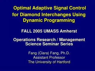
Gen. #1: Trans. Line Impedance Increase 1.01 1 Terminal voltage in pu 0.99 CONV_CONV 0.98 CONV_PSS_CONV 0.97 DHP_CONV 10 10.5 11 11.5 12 12.5 13 13.5 14 14.5 Time in seconds 40 35 Load angle in degrees CON_CONV 30 CONV_PSS_CONV 25 DHP_CONV 20 10 10.5 11 11.5 12 12.5 13 13.5 14 14.5 15 Time in seconds