Download
1 / 26
260 likes | 405 Vues
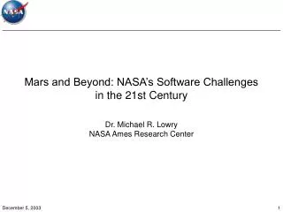
Mars and Beyond: NASA’s Software Challenges in the 21st Century. Dr. Michael R. Lowry NASA Ames Research Center. Outline. NASA’s Mission Role of Software within NASA’s Mission The Challenge: Enable Dependable SW-based Systems Technical Challenges Scaling ! System-software barrier

E N D
Mars and Beyond: NASA’s Software Challenges in the 21st Century Dr. Michael R. Lowry NASA Ames Research Center
Outline • NASA’s Mission • Role of Software within NASA’s Mission • The Challenge: Enable Dependable SW-based Systems • Technical Challenges • Scaling ! • System-software barrier • Software is opaque and brittle in the large • Reasons for Optimism
NASA’s Vision NASA’s Mission • To understand and protect our home planet • To explore the universe and search for life • To inspire the next generation of explorers • …as only NASA can To improve life here To extend life to there To find life beyond Biological & Physical Research 5 Strategic EnterprisesOne NASA Space Science Earth Science Aerospace Technology HEDS
Software Growth in Aerospace MissionsSoftware Enables NASA’s Missions F-22 (PROJECTED) 10,000 SHUTTLE/ OPERATIONAL Piloted Systems B-2 F-15E SHUTTLE/OFT 1,000 C-17 PROJECTED B-1B B-1A F-16 C/D Instructions (Equivalent Memory Locations in K) Unpiloted Systems AWACS GEMINI 8 100 GALILEO P-3A MISSILE PERSHING 11 APOLLO 7 F-111 VIKING F-111 MERCURY 3 PERSHING 11 (AO) GEMINI 3 C-5A 10 TRIDENT C4 A7D/E GEMINI 3 VOYAGER PERSHING 1 TITAN 111C TITAN POSEIDON C3 MARINER PERSHING 1A VENUS 1 SURVEYOR MERCURY 1960 1965 1970 1975 1980 1985 1990 1995 Year (Doubling every 3 or 4 years) Source: AF Software Technology Support Center
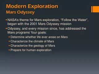
Mars Climate Orbiter • Launched • 11 Dec 1998 • Mission • interplanetary weather satellite • communications relay for Mars Polar Lander • Fate: • Arrived 23 Sept 1999 • No signal received after initial orbit insertion • Cause: • Faulty navigation data caused by failure to convert imperial to metric units
MCO Events • Locus of error • Ground software file called “Small Forces” gives thruster performance data • This data is used to process telemetry from the spacecraft • Spacecraft signals each Angular Momentum Desaturation (AMD) maneuver • Small Forces data used to compute effect on trajectory • Software underestimated effect by factor of 4.45 • Cause of error • Small Forces Data given in Pounds-seconds (lbf-s) • The specification called for Newton-seconds (N-s) • Result of error • As spacecraft approaches orbit insertion, trajectory is corrected • Aimed for periapse of 226km on first orbit • Estimates were adjusted as the spacecraft approached orbit insertion: • 1 week prior: first periapse estimated at 150-170km • 1 hour prior: this was down to 110km • Minimum periapse considered survivable is 80km • MCO entered Mars occultation 49 seconds earlier than predicted • Signal was never regained after the predicted 21 minute occultation • Subsequent analysis estimates first periapse of 57km
First 4 months, AMD data unusable due to file format errors Navigators calculated the data by hand File format fixed by April 1999 Anomalies in the computed trajectory became apparent almost immediately Limited ability to investigate the anomalies: Thrust effects measured along Earth-spacecraft line of sight using doppler shift AMD thrusts are mainly perpendicular to line of sight Failure to communicate between teams: E.g. Issue tracking system not properly used by navigation team Anomalies were not properly investigated Inadequate staffing Operations team were monitoring three missions simultaneously (MGS, MCO and MPL) Operations Navigation team unfamiliar with spacecraft Different team from the development and test team This team did not fully understand the significance of the anomalies Assumed familiarity with previous mission (Global Surveyor) was sufficient: did not understand why AMD was performed 10-14 times more often (MCO has asymmetric solar panels, whereas MGS had symmetric panels) Inadequate Testing Software Interface Specification was not used during unit testing of small forces software End-to-end test of ground software was never completed Ground software was not considered “mission critical” so didn’t have independent V&V Inadequate Reviews Key personnel missing from critical design reviews Contributing Factors
Analysis Errors SW Size • Software size, S, increasing exponentially(doubling every three or four years) • Errors, cost over-runs, schedule slip due primarily to non-local dependencies during integration (SN, with N<2, best calibration: N=1.2 ) Source: Professor Barry Boehm, Author of Software Cost Modeling
Predicted Errors as LOC Grows:Current SW Practices/Technology Cassini MPL Errors = e SN; where S is the number of modules (LOC/M), and error rate e = 1/10,000
Technical Challenges and Opportunities • System-software barrier • (Verification is easy, validation is hard) • Software is transparent and malleable in the small… • But opaque and brittle in the large • General-purpose software dependability tools work well in the small • But fail to scale to systems in the large. But there is Reason for Optimism Align software architectures with system analysis Success of formal methods in related field of digital hardware Scaling through specialization Divide and Conquer: compositional reasoning Beyond correctness: exploiting the lattice between true and false for software understanding Providing the research community with realistic experimental testbeds at scale
Scaling through Specialization:Practical Static Analysis Scalability 1 MLoc C Global Surveyor (NASA Ames) Coverity 500 KLoc DAEDALUS PolySpace C-Verifier 50 KLoc Precision 80% 95% SPECIALIZED ANALYZERS GENERAL-PURPOSE ANALYZERS
void add(Object o) { buffer[head] = o; head = (head+1)%size; } Object take() { tail=(tail+1)%size; return buffer[tail]; } Software Model CheckerJPF Code with Transient Error Produces Error Trace Localize Causeof the Error ErrorExplanation void add(Object o) { buffer[head] = o; head = (head+1)%size; } Object take() { tail=(tail+1)%size; return buffer[tail]; } void add(Object o) { buffer[head] = o; head = (head+1)%size; } Object take() { tail=(tail+1)%size; return buffer[tail]; } • 1. Source code similarities to explain control errors • code that appear only in negatives • all negatives, and, • only and all negatives (causal) • 2. Data invariants – explains errors in data • 3. Minimal transformations to create a negative from a positive – show the essence of an error Explaining the Cause of an Error A model checker can automatically find a trace that show the error appearing Hard to Show Error Testing cannot reliably show the error appearing, since it may require specific environment actions (inputs) or scheduling (for concurrency errors) + Hard to Find Cause of the Error Once we know a way to show the error it is difficult to localize the root cause of the error Now we can automatically find an explanation for the error from the error trace produced by the model checker and the original program The algorithm uses model checking to first find similar traces that also cause the error (negatives) and traces that do not cause the error (positives) Set of PositivesTraces that don’t show the error Set of Negatives Traces that show different versions of the error Analysis
Rover Executive void Executive:: startExecutive(){ runThreads(); …} void Executive:: executePlan(…) { while(!empty) executeCurrentPlanNode(); } … Structural Constraints Lazy initialization+ Enumerate all structures Code class Node { int elem; Node next; Node deleteFirst() { if (elem < 10) return next; else if (elem < 0) assert(false); … } } Decision procedures continue/ backtrack null e0 e0 input program instrumented program Program instrumentation Model checking correctness specification counterexample(s)/ test suite [heap+constraint+thread scheduling] Generalized Symbolic Execution for Model Checking and Testing • Future mission software: • concurrent • complex, dynamically allocated data • structures (e.g., lists or trees) • highly interactive: • with complex inputs • large environment • - should be extremely reliable Input plan execute action environment/ rover status complex input structure concurrency, dynamic data (lists, trees) large environment data Current practice in checking complex software: - testing: - requires manual input - typically done for a few nominal input cases - not good at finding concurrency bugs - not good at dealing with complex data structures - model checking: - automatic, good at finding concurrency bugs - not good at dealing with complex data structures - feasible only with a small environment - and a small set of input values Our novel symbolic execution framework: - extends model checking to programs that have complex inputs with unbounded (very large) data - automates test input generation e0 true false Analysis of “deleteFirst” with our framework e0 < 10 e0 ≥ 10 Framework: true e0 ≥ 10 /\ e0<0 e0 e1 FALSE Precondition: acyclic list • “simulate” the code using symbolic values instead of program data; enumerate the input structures lazily Numeric Constraints Decision Procedures - modular architecture: can use different model checkers/decision procedures ( = “unknown yet”)
System-Level Verification • check (system-level) integration properties based on module specifications • module hierarchy and interfaces used for incremental abstraction • architectural patterns potentially reusable • generate module/environment assumptions • check implementation modules against their design specifications • monitor properties that cannot be verified • monitor environment assumptions
Module Verification how are assumptions obtained? • Developer encodes them • Abstractions of environment, if known Automated Software Engineering 2002 • Automatically generate exact assumption A • for any environment E (E || Module ╞ Property) IFF E╞ A • Demonstrated on Rover example • Modules may require context information to satisfy a property • Assumption || Module ╞ Property (assume – guarantee reasoning) Module Property a c b Assumption Environment
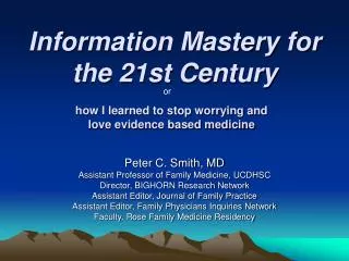
Mission Manager Viewpoint Asking the Right Questions When can we stop testing? What process should we use? What is the value of formal methods? Qualitative Correlative Model Peer Review superior to testing for incorrect spec Model Checking for uncertain environments Quantitative Predictive Model Mission trade studies: how muchcost for acceptable risk Development: optimize use of Assurance technologies Mission: increase use of CPUcycles for software monitoring
HDCP Goals The overall mission of the HDCP project is to increase the ability of NASA to engineer highly dependable software systems Method: • Science of Dependability: • Develop better ways to measure and predict software dependability • What are the potential measurables for the various attributes? • How can we move past the present surrogates and approach the artifact more directly? • Empirical evaluation • of NASA and NASA-contractor dependability problems • of technologies and engineering principles to address the problems • Testbeds • Development of realistic testbeds for empirical evaluation of technologies and attributes. • Intervention technologies
Active MDS Testbed Projects • Golden Gate Project • Demonstrate that RT-Java is suitable for mission systems • Drive MDS/RTSJ rover at JavaOne • Collaborators: Champlin, Giovannoni • SCRover Project • Develop rover testbed • Collection defect and process data for experience base • Collaborators: Boehm, Madachy, Medvidovic, Port • Dependability cases • Develop dependability cases for time management and software architectures • Collaborators: Goodenough, Weinstock, Maxion, Hudak • Analysis of MDS architectural style • Analysis based on MDS use architectural-components types • Collaborators: Garlan • Process improvement • Data collection from mainline MDS and SCRover development efforts • Collaborators: Johnson, Port
MDS in 1 Minute MDS Products • Unified flight, ground and test architecture • Orderly systems engineering methodology • Frameworks (C++ and Java) • Processes, tools, and documentation • Examples • Reusable software • Problem Domain Mission information, control, and operations of physical systems • Developed for unmanned space science missions • Scope includes flight, ground and simulation/test • Applicable to robots that operate autonomously to achieve goals specified by humans • Architecturally suited for complex systems where “everything affects everything” • Approach Product line practice to exploit commonalities across missions: • An information and control architecture to which missions/products conform • A systems engineering process that is analytical, disciplined, and methodical • Reusable and adaptable framework software
Managing Interactions • State-BasedArchitecture • Handles interactionsamong elementsof the system under control • Outward looking • Addresses systemsengineering issues • Component-Based • Architecture • Handles interactionsamong elementsof the system software • Inward looking • Addresses softwareengineering issues “A unified approach to managing interactions is essential” • Complex interactions make software difficult • Elements that work separately often fail to work together • Combinatorics of interaction is staggering, so it’s not easy to get right • This is a major source of unreliability • There are two approaches to this in MDS:
MDS is…State-Based Architecture State variables hold state values, including degree of uncertainty A goal is a constraint on the value of a state variable over a time interval Estimators interpret measurement and command evidence to estimate state Models express mission-specific relations among states, commands, and measurements Controllers issue commands, striving to achieve goals Hardware proxies provide access to hardware busses, devices, instruments Key Features: • Systems analysis/design organized around states and models • State control architecturally separated from state determination • System operated via specifications of intent: goals on state
From theory to flight...JPL Transition Path • Mars Smart Lander (MSL) Technology Infusion • Scheduled Launch: 2009 • MSL has baselined MDS technology • System engineering • Software frameworks • MSL Technology Gates • PMSR August, 2004 • Integrated demoJune, 2005 • PDR February, 2006 • MSL sample technology categories • Software architecture with infused technologies • Verification and Validation tools and methodologies • Processes and supporting tools • Cost modeling for system engineering, software adaptation and autonomy validation MDS compatible technologies are directly relevant to MSL
Conclusions • System-software barrier • (Verification is easy, validation is hard) • Software is transparent and malleable in the small… • But opaque and brittle in the large • General-purpose software dependability tools work well in the small • But fail to scale to systems in the large. But there is Reason for Optimism Align software architectures with system analysis Success of formal methods in related field of digital hardware Scaling through specialization Divide and Conquer: compositional reasoning Beyond correctness: exploiting the lattice between true and false for software understanding Providing the research community with realistic experimental testbeds at scale