Download
1 / 41
1.64k likes | 7.9k Vues
1D, Steady State Heat Transfer with Heat Generation Fins and Extended Surfaces. Chapter 3c : One-dimensional, Steady state conduction (with thermal energy generation) (Section 3.5 – Textbook). 3.1 Implications of energy generation.

E N D
1D, Steady State Heat Transfer with Heat Generation Fins and Extended Surfaces
Chapter 3c : One-dimensional, Steady state conduction (with thermal energy generation) (Section 3.5 – Textbook) 3.1 Implications of energy generation • Involve a local source of thermal energy due to conversion from another form of energy in a conducting medium. • The source may be uniformly distributed, as in the conversion from electrical to thermal energy • or it may be non-uniformly distributed, as in the absorption of radiation passing through a semi-transparent medium • Generation affects the temperature distribution in the medium and causes the heat rate to vary with location, thereby precluding inclusion of the medium in a thermal circuit. (Cannot use electrical analogy!) Eq. (1.11c)
Chapter 3 : One-dimensional, Steady state conduction (without thermal generation) *Recall previous case: a steady state plane wall with constant k & no heat generation Assuming steady-state conditions and no internal heat generation (i.e. q = 0), then the 1-D heat conduction equation reduces to: . For constantk and A This means: Heat flux (q”x) is independent of x Heat rate (qx) is independent of x Boundary conditions: T(0) = Ts,1 T(L) = Ts,2
Chapter 3 : One-dimensional, Steady state conduction (with thermal generation) 3.2 A plane wall with internal heat generation *Consider a plane wall between two fluids ofdifferent temperatures Assuming steady-state conditions and internal heat generation (i.e. q = 0), from the 1-D heat conduction equation: . - general heat equation reduces to: This means: Heat flux (q”x) is not independent of x Heat rate (qx) is not independent of x Boundary conditions: T(-L) = Ts,1 T(L) = Ts,2
Chapter 3 : One-dimensional, Steady state conduction (with thermal generation) , for constant k and A 2nd order DE: Integrate twice to get T(x) for boundary conditions: at x = -L, T(-L) = Ts,1 , at x = L, T(L) = Ts,2 This gives, and Substituting the values for C1and C2 into eq. T(x) Temperature distribution equation
Chapter 3 : One-dimensional, Steady state conduction (with thermal generation) Then, apply Fourier’s Law to get heat transfer (BUT qx is now dependent on x) Heat flux (W/m2): Heat rate (W):
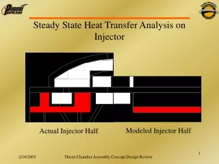
Chapter 3 : One-dimensional, Steady state conduction (with thermal generation) What happens if both surfaces are maintained at the same temperature, Ts,1 = Ts,2 = Ts This case is called A case of symmetric surface conditions or one surface was insulated. Therefore, the temperature distribution eq. reduces to : Eq. (3.42) The max temperature exists at the mid plane: Eq. (3.43) Rearranging the temp distribution *this means, at the plane of symmetry the temp gradient is ZERO.
Chapter 3 : One-dimensional, Steady state conduction (with thermal generation) Symmetric surface conditions or one surface was insulated. • Because the temp gradient at the centerline is zero, there is ZERO heat flow at that point and it behaves like an insulated wall. • The insulated wall has the same parabolic temperature profile as half the un-insulated full wall *recall the previous chapter: Boundary conditions (Table 2.2)
Chapter 3 : One-dimensional, Steady state conduction (with thermal generation) Symmetric surface conditions or one surface was insulated. • Because the temp gradient at the centerline is zero, there is ZERO heat flow at that point and it behaves like an insulated wall. • The insulated wall has the same parabolic temperature profile as half the un-insulated full wall • Why does the magnitude of the temperature gradient increase with increasing x ?
Chapter 3 : One-dimensional, Steady state conduction (with thermal generation) Symmetric surface conditions or one surface was insulated. • Because the temp gradient at the centerline is zero, there is ZERO heat flow at that point and it behaves like an insulated wall. • The insulated wall has the same parabolic temperature profile as half the un-insulated full wall • Why does the magnitude of the temperature gradient increase with increasing x ? - due to increase in temperature difference
Chapter 3 : One-dimensional, Steady state conduction (with thermal generation) Symmetric surface conditions or one surface was insulated. • Because the temp gradient at the centerline is zero, there is ZERO heat flow at that point and it behaves like an insulated wall. • The insulated wall has the same parabolic temperature profile as half the un-insulated full wall • Why does the magnitude of the temperature gradient increase with increasing x ? • How do we determine Ts ? - due to increase in temperature difference
Chapter 3 : One-dimensional, Steady state conduction (with thermal generation) Symmetric surface conditions or one surface was insulated. • Because the temp gradient at the centerline is zero, there is ZERO heat flow at that point and it behaves like an insulated wall. • The insulated wall has the same parabolic temperature profile as half the un-insulated full wall • Why does the magnitude of the temperature gradient increase with increasing x ? • How do we determine Ts ? • How do we determine the heat rate at x = L ? (no energy in, neglecting radiation, energy balance becomes)
Chapter 3 : One-dimensional, Steady state conduction (with thermal generation) Symmetric surface conditions or one surface was insulated. • Because the temp gradient at the centerline is zero, there is ZERO heat flow at that point and it behaves like an insulated wall. • The insulated wall has the same parabolic temperature profile as half the un-insulated full wall • Why does the magnitude of the temperature gradient increase with increasing x ? • How do we determine Ts ? • How do we determine the heat rate at x = L ? (Neglecting radiation, energy balance becomes) Using the surface energy balance, energy generated must equal to energy outflow
Chapter 3c : One-dimensional, Steady state conduction (with thermal energy generation) • Referring to the Example 3.7 in textbook Parabolic in material A Zero slope at insulated boundary Linear slope in material B Slope change kB/kA=2 at interface Large gradients near the surface
Chapter 3c : One-dimensional, Steady state conduction (with thermal energy generation) Example (3.74): Consider a plane composite wall that is composed of three materials (materials A,B and C are arranged left to right) of thermal conductivities kA=0.24 W/mK, kB=0.13 W/mK and kC=0.50 W/mK. The thickness of the three sections of the wall are LA= 20mm, LB= 13mm and LC= 20mm. A contact resistance of R”t,c=10-2m2K/W exists at the interface between materials A and B, as well as interface between B and C. The left face of the composite wall is insulated, while the right face is exposed to convective conditions characterised by h=10 W/m2K, T=20C. For case 1, thermal energy is generated within material A at rate 5000 W/m3. For case 2, thermal energy is generated within material C at rate 5000 W/m3. Determine the maximum temperature within the composite wall under steady state conditions for Case 1 Sketch the steady state temperature distribution on T-x coordinates for Case 1 Find the maximum temperature within the composite wall and sketch the steady state temperature distribution for Case 2
Chapter 3c : One-dimensional, Steady state conduction (with thermal energy generation) 3.3 Radial systems (cylinder and sphere)
Chapter 3c : One-dimensional, Steady state conduction (with thermal energy generation) • Temp distribution for solid cylinder: • Eq. (3.53) or • (C.23) • Temp distribution for hollow cylinder: • Eq. (C.2)
Chapter 3c : One-dimensional, Steady state conduction (with thermal energy generation) • Temp distribution for solid sphere: • Eq. (C.24) • Temp distribution for spherical wall: • Eq. (C.3) *A summary of temp distributions, heat fluxes & heat rates for all cases is provided in Appendix C.
Chapter 3c : One-dimensional, Steady state conduction (with thermal energy generation) Problem 3.92: A long cylindrical rod of diameter 200 mm with thermal conductivity of 0.5 W/mK experiences uniform volumetric heat generation of 24,000 W/m3. The rod is encapsulated by a circular sleeve having an outer diameter of 400 mm and a thermal conductivity of 4 W/mK. The outer surface of the sleeve is exposed to cross flow of air at 27C with a convection coefficient of 25 W/m2K. Find the temperature at the interface between the rod and sleeve and on the outer surface. What is the temperature at the center of the rod ?
Chapter 3c : One-dimensional, Steady state conduction (with thermal energy generation) Problem 3.95: Radioactive wastes (krw=20 W/mK) are stored in a spherical stainless steel (kss=15 W/mK) container of inner and outer radii equal to ri=0.5 m and ro=0.6 m. Heat is generated volumetrically within the wastes at a uniform rate of 105 W/m3, and the outer surfaces of the container is exposed to a water flow for which h=1000 W/m2K and T=20C Evaluate the steady-state outer surface temperature, Ts,o Evaluate the steady-state inner surface temperature, Ts,i Obtain an expression for the temperature distribution, T(r), in the radioactive wastes. Express your result in term of ri, Ts,i, krw and q. Evaluate the temperature at r = 0 .
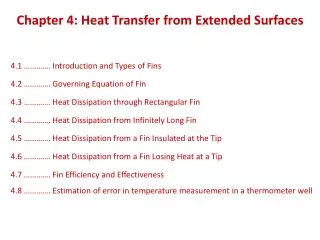
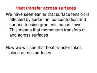
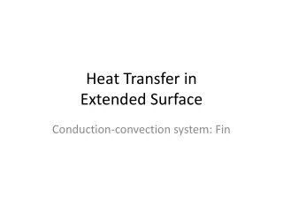
Chapter 3d : Heat transfer from extended surface (Section 3.6 – Textbook) 3.1 Introduction • Extended surface (also known as fins) is commonly used to depict an important special case involving combination of conduction-convection system. • Consider a strut that connects two walls at different temperatures and across which there is fluid flow
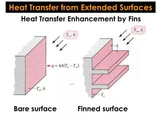
Chapter 3d : Heat transfer from extended surface 3.1 Introduction • Extended surface (also known as fins) is commonly used to depict an important special case involving combination of conduction-convection system. • Why its important ? The most frequent application to enhance heat transfer between a solid joining and an adjoining fluid • Basically, there are 2 ways of increasing heat transfer • Increase fluid velocity to reduce temperature (many limitation) • Increase surface area *Particularly beneficial when h is small i.e. gas and natural convection
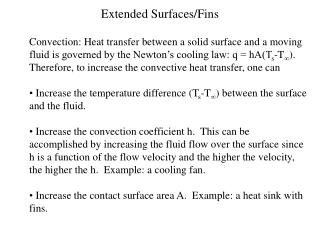
Chapter 3d : Heat transfer from extended surface • Applications ?
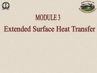
Chapter 3d : Heat transfer from extended surface • Typical fin configurations (after simplification) Figure 3.14 Straight fins of (a) uniform; (b) non-uniform cross sections; (c) annular fin; (d) pin fin of non-uniform cross section
Chapter 3d : Heat transfer from extended surface 3.2 A general conduction analysis for an extended surfaces Applying the conservation of energy Using, Then, the heat equation becomes: Eq. (3.61) General form of the energy equation for an extended surface
Chapter 3d : Heat transfer from extended surface 3.3 The Fin Equation • Assuming 1-D case, steady state conduction in an extended surface, constant k, uniform cross sectional area, negligible generation and radiation. • Cross section area, Ac is constant and fin surface area, As = Px, this mean dAc/dx = 0 and dAs/dx = P • General equation becomes: Eq. (3.62)
Chapter 3d : Heat transfer from extended surface • To simplify the equation, we define an excess temperature ( the reduced temperature) as: • The previous equation becomes: • where, Eq. (3.63) Eq. (3.65) P is the fin perimeter * m also known as fin parameter
Chapter 3d : Heat transfer from extended surface By referring to Table 3.4 : at different case of heat transfer analysis • Temperature distribution, /b
Chapter 3d : Heat transfer from extended surface Example (3.120): A brass rod 100 mm long and 5 mm in diameter extends horizontally from a casting at 200C. The rod is in an air environment with T = 20C and h = 30 W/m2K. What is the temperature of the rod at 25, 50 and 100 mm from the casting body ?
Chapter 3d : Heat transfer from extended surface 3.4 Fin performance parameters (single fin case) • Fin effectiveness – ratio of heat transfer with and without fin Eq. (3.81) • Fin resistance Eq. (3.83) and (3.92) • Fin efficiency – max. potential heat transfer rate Eq. (3.86) Expressions for f are provided in Table 3.5 for common geometries, for example a triangular fin: - Surface area of the fin - Profile area
Chapter 3d : Heat transfer from extended surface Example (3.123): A straight fin fabricated from 2024 aluminium alloy (k = 185 W/mK) has a base thickness of t = 3 mm and a length of L = 15 mm. Its base temperature is Tb = 100 C, and it is exposed to a fluid for which T = 20C and h = 50 W/m2K. For the foregoing conditions and a fin of unit width, compare the fin heat rate, efficiency and volume for Rectangular profile Triangular profile Parabolic profile
Chapter 3d : Heat transfer from extended surface • 3.5 Fin arrays • Representative arrays of • a) Rectangular fins • b) Annular fins • Eq. (3.99) • Eq. (3.100) • Eq. (3.102) • Eq. (3.103)
Chapter 3d : Heat transfer from extended surface • Previous equations are for fins that are produced by machining or casting which as an integral part of the wall ( as in Fig. 3.20 & Fig 3.21a) • Eq. (3.102) • Eq. (3.103)
Chapter 3d : Heat transfer from extended surface • However, some fins are manufactured separately and attached by a metallurgical or adhesive joint or press fit. Such cases need to consider contact resistance (as in Fig 3.21b) • Eq. (3.105a) • Eq. (3.105b) • Eq. (3.104)