Microcomputers & Microprocessors
Microcomputers & Microprocessors. Khaled A. Al- Utaibi alutaibi@uoh.edu.sa. Agenda. What is a Microcomputer ? Course Objectives The Stored Program Concept The Stored Program Processing Cycle Fetch, Decode and Execute The Instruction Set Modern CPUs Three-Bus System Architecture

Microcomputers & Microprocessors
E N D
Presentation Transcript
Microcomputers & Microprocessors Khaled A. Al-Utaibi alutaibi@uoh.edu.sa
Agenda • What is a Microcomputer ? • Course Objectives • The Stored Program Concept • The Stored Program Processing Cycle • Fetch, Decode and Execute • The Instruction Set • Modern CPUs • Three-Bus System Architecture • The Data Bus • The Memory Banks • The Address Bus • The Control Bus • The 80x86 Family
What is a Microcomputer ? • A microcomputer is an electronic device with a microprocessor as its central processing unit (CPU), a memory, and input/output (I/O) facilities.
What is a Microcomputer ? • When a microcomputer is equipped with a keyboard and screen for input and output and is running an operatingsystem(DOS, Windows, Linux, etc) it is called a personalcomputer.
Course Objectives • To introduce the fundamental hardware and software concepts needed for the design of microcomputers system.
Course Objectives • To introduce the fundamental hardware and software concepts needed for the design of microcomputers system. • Functions of various processor pins • Memory/IO Read and Write bus cycles • Main types of memory technology • Memory internal organization • Design memory interfaces. • Computer serial and parallel interfaces
Course Objectives • To introduce the fundamental hardware and software concepts needed for the design of microcomputers system. • How interrupts are used to implement I/O control and data transfers • Design interrupt service routines and I/O drivers using assembly language. • Data access from magnetic and optical disk drives using DMA • Types of bus interfaces in a computer system
The Stored Program Concept • Most of today’s computer systems are based on a design principle proposed by Dr. John Von Neumann (1946).
Stored Program Computer • The basic stored program computer (Von Neumann Architecture) consists of three major parts: (1) CPU, (2) Memory, (3) I/ODevices.
Stored Program Processing Cycle • The basic stored program cycle consists of three major steps: (1) Fetch, (2) Decode, (3) Execute.
Stored Program Processing Cycle • Clock Generator: • Controls the basic timing of the computer • It generates a square wave signal • This signal is used to synchronize all activities within the computer • Registers: • Two types (general purpose, special purpose) • General purpose registers are used to store temporary information • Special purpose registers are used for specific tasks (e.g. the accumulator)
Stored Program Processing Cycle • Fetching, Decoding and Executing an Instruction: • The basic processing cycle begins with a memoryfetchor read cycle • The InstructionPointer(IP) holds the address of next instruction to be fetched. • This address is output on the systemaddressbus. • The memory addressdecoder examines the binary value of the address on the system address bus and selects the proper memory location.
Stored Program Processing Cycle • Fetching, Decoding and Executing an Instruction: • The CPU activate the memoryreadcontrolthrough the systemcontrolbus. • This causes the selected data byte (i.e. instruction) in the memory to be placed onto thedatabus. • The instruction is then placed in the InstructionRegister(IR). • Once in the CPU, the instruction is decoded and executed. • When executing the instruction is completed, the cycle is repeated.
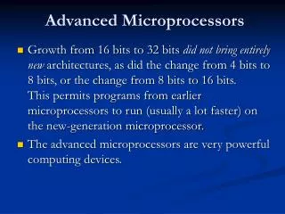
Stored Program Processing Cycle • The Instruction Set: • The job of the InstructionDecoder(ID) is to recognize and activate appropriate controls in the CPU needed to execute the instruction. • The list of all instructions recognized by the ID is called the instructionset. • Microprocessors are classified based on the specification of the instruction sets into two categories: • (1) Complex Instruction Set Computers (CISC) and • (2) Reduced Instruction Set Computers (RISC)
Stored Program Processing Cycle • Modern CPUs: • Most microprocessors today are designed to allow the fetch and execute cycles to overlap. • This is done by dividing the CPU into two units: • (1) a Bus Interface Unit (BIU) and • (2) an Execution Unit (EU). • The job of the BIU is to fetch instructions from memory and store them in a special instructionqueue. • The EU then fetches instructions from this queue (not from memory). • Some processors have a pipelined execution unit that allows the decoding and execution of instructions to overlap.
Three-Bus System Architecture • A bus is a collection of electronic signal lines all dedicated to a particular task. • The architecture considered in the previous slides consists of three types of buses: address, data, and control buses.
Three-Bus System Architecture • The Data Bus: • The data bus consists of internal and external data buses. • The internal data bus connects the internalcomponentsof the CPU (e.g. Registers, ALU, etc.) to the dataI/Opinsof the CPU. • The external data bus connects the dataI/Opinsof the CPU to the memory and I/Odevices(e.g. printer, monitor, etc). • The width of the internal data bus in bits is usually used to classify a microprocessor (e.g. 8-bit, 16-bit, 32-bi microprocessors)
Three-Bus System Architecture • The Data Bus: • The width of the internal data bus is usually the same as the external data bust – but not always. • The 80386processorhas 32-bit internal and 32-bit external data buses. • The 80386SXprocessorhas 32-bit internal data bus, but 16-bit external data bus. • The Pentiumprocessorhas 32-bit internal data bus and 64-bit external data bus.
Three-Bus System Architecture • Memory Banks: • How a 64-bit (or 32-bit or 16-bit) processor can access an 8-bit-wide memory? • The memory is divided into banks. • The 8086processor(16-bit) requires 2banks(16/8=2).
Three-Bus System Architecture • Memory Banks: • How a 64-bit (or 32-bit or 16-bit) processor can access an 8-bit-wide memory? • The memory is divided into banks. • The 80486processor(32-bit) requires 4banks(32/8=4).
Three-Bus System Architecture • The address Bus: • It is used to identify the memory location or I/O device (also called I/O port) to be accessed by the CPU • The width of this bus in the 80x86familyvaries from one processor to the other for example: • The 8086/8088 processorshave 20-bit address bus. • The 80286 processorhas 24-bit address bus. • The 80386/80486/Pentium processorshave 32-bit address bus. • The Pentium Pro processor has 36-bit address bus.
Three-Bus System Architecture • Example 1: How many different memory addresses can an 8086 output? Repeat for 80286 and 80386 processors.
Three-Bus System Architecture • Example 1: How many different memory addresses can an 8086 output? Repeat for 80286 and 80386 processors. • 8086 processor has 20 address lines • Addressable memory locations = 220 = 1M • 80286 processor has 24 address lines • Addressable memory locations = 224 = 24x220 = 16M • 80386 processor has 32 address lines • Addressable memory locations = 232 = 22x230 = 4G
Three-Bus System Architecture • The Control Bus: • How can we tell if the address on the address bus is a memory address or an I/O port ? • How can we tell if the memory or I/O access is a read or write operation ? • These questions are answered by the control bus. • Each time the processor outputs an address, it also activates one of 4 control signals • (1) Memory Read • (2) Memory Write • (3) I/ORead • (4) I/OWrite
The 80x86 Family • The 8086 Microprocessor (1978): • 20-bit address bus. • 16-bit internaldatabus. • 16-bit externaldatabus. • Separate businterfaceunit(BIU) and executionunit(EU). • 16-bit registers (with the ability to access the high or low 8 bits separately). • Built in hardwaremultiply and divide instructions. • Support for an externalfloating-pointmathcoprocessor.
The 80x86 Family • The 8088 Microprocessor (1979): • 20-bit addressbus. • 16-bit internaldatabus. • 8-bit externaldatabus. • Separate businterfaceunit(BIU) and executionunit(EU). • 16-bit registers (with the ability to access the high or low 8 bits separately). • Built in hardwaremultiply and divide instructions. • Support for an externalfloating-pointmathcoprocessor.
The 80x86 Family • The 80186 & 80188 Microprocessors (1982): • A personal computer (PC) based on the 8086/8088 microprocessors requires several additional chips such as: a clock generator, a programmable timer, a programmable interrupt controller, a direct memory access controllerand a circuitry to select the I/O devices. • To simplify the design, Intel introduced the 80186 & 80188 microprocessors. • The 80186/80188 integrates on a single chip an 8086/8088 microprocessor and all the chips mentioned above. • The 80186 & 80188 are often referred to as high-integration processors • Used as a microcontroller
The 80x86 Family • The 80286 Microprocessor (1982): • 24-bit addressbus. • 16-bit internaldatabus. • 16-bit externaldatabus. • Designed to be softwarecompatiblewith 8086 & 80186 microprocessors. • Provides two programming modes: • Real Mode • Protected Mode
The 80x86 Family • The 80286 Microprocessor (Real Mode): • The processor function exactly like the 8086 processor. • That is, any 8086 program can be run on a Real Mode 80286 processor without any change. • The 80286 processor uses only its 20 least significant address lines. • So, the memory space is limited to 1 MB.
The 80x86 Family • The 80286 Microprocessor (Protected Mode): • In this mode, the processor supports a multiprogram environment. • It gives each program a predetermined amount of memory. • This uses the full memory space which is 16MB. • This mode is called Protected Mode because several programs can be loaded into memory at once (each in its own segment), but are protected from each other.
The 80x86 Family • The 80386 Microprocessor (1984): • 32-bit address bus. • 32-bit internal data bus. • 32-bit external data bus. • 32-bit registers. • Provides three modes: • Real Mode (identical to that of 80286) • Protected Mode (manages 4 GB of memory in a way similar to that of the 80286). • Virtual Mode (similar to Real Mode, except that multiple 8086 processors can run simultaneously
The 80x86 Family • The 80386 Microprocessor (1989): • 32-bit address bus. • 32-bit internalandexternaldatabus. • 32-bit registers. • On-chip cache (stores the most recently used instructions and data ) • Integrated Floating-Point Unit (FPU) • Real & Protected Modes as in 80386 • Pipelined design
The 80x86 Family • The Pentium Microprocessor (1993): • 32-bit addressbus. • 32-bit internal • 64-bitexternaldatabus. • 32-bit registers. • Two instructions pipelines • On-chip cache • Integrated FPU