Chapter 10: IC Technology
Chapter 10: IC Technology. Outline. Anatomy of integrated circuits Full-Custom (VLSI) IC Technology Semi-Custom (ASIC) IC Technology Programmable Logic Device (PLD) IC Technology. CMOS transistor. Source, Drain Diffusion area where electrons can flow

Chapter 10: IC Technology
E N D
Presentation Transcript
Outline • Anatomy of integrated circuits • Full-Custom (VLSI) IC Technology • Semi-Custom (ASIC) IC Technology • Programmable Logic Device (PLD) IC Technology
CMOS transistor • Source, Drain • Diffusion area where electrons can flow • Can be connected to metal contacts (via’s) • Gate • Polysilicon area where control voltage is applied • Oxide • Si O2 Insulator so the gate voltage can’t leak
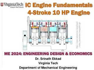
gate oxide IC package IC source channel drain Silicon substrate End of the Moore’s Law? • Every dimension of the MOSFET has to scale • (PMOS) Gate oxide has to scale down to • Increase gate capacitance • Reduce leakage current from S to D • Pinch off current from source to drain • Current gate oxide thickness is about 2.5-3nm • That’s about 25 atoms!!!
20Ghz + • FinFET has been manufactured to 18nm • Still acts as a very good transistor • Simulation shown that it can be scaled to 10nm • Quantum effect start to kick in • Reduce mobility by ~10% • Ballistic transport become significant • Increase current by about ~20%
NAND • Metal layers for routing (~10) • PMOS don’t like 0 • NMOS don’t like 1 • A stick diagram form the basis for mask sets
Silicon manufacturing steps • Tape out • Send design to manufacturing • Spin • One time through the manufacturing process • Photolithography • Drawing patterns by using photoresist to form barriers for deposition
Full Custom • Very Large Scale Integration (VLSI) • Placement • Place and orient transistors • Routing • Connect transistors • Sizing • Make fat, fast wires or thin, slow wires • May also need to size buffer • Design Rules • “simple” rules for correct circuit function • Metal/metal spacing, min poly width…
Full Custom • Best size, power, performance • Hand design • Horrible time-to-market/flexibility/NRE cost… • Reserve for the most important units in a processor • ALU, Instruction fetch… • Physical design tools • Less optimal, but faster…
Semi-Custom • Gate Array • Array of prefabricated gates • “place” and route • Higher density, faster time-to-market • Does not integrate as well with full-custom • Standard Cell • A library of pre-designed cell • Place and route • Lower density, higher complexity • Integrate great with full-custom
Semi-Custom • Most popular design style • Jack of all trade • Good • Power, time-to-market, performance, NRE cost, per-unit cost, area… • Master of none • Integrate with full custom for critical regions of design
Programmable Logic Device • Programmable Logic Device • Programmable Logic Array, Programmable Array Logic, Field Programmable Gate Array • All layers already exist • Designers can purchase an IC • To implement desired functionality • Connections on the IC are either created or destroyed to implement • Benefits • Very low NRE costs • Great time to market • Drawback • High unit cost, bad for large volume • Power • Except special PLA • slower 1600 usable gate, 7.5 ns $7 list price