UNIT 8: Synthesis Basics
260 likes | 276 Vues
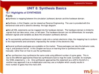
Learn the basics of synthesis and how to manually map behavioral code to logic diagrams. Understand the limitations and constraints of the hardware domain and the requirements of electronic chip vendors.

UNIT 8: Synthesis Basics
E N D
Presentation Transcript
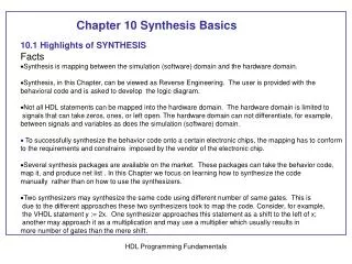
UNIT 8: Synthesis Basics • 10.1 Highlights of SYNTHESIS • Facts • Synthesis is mapping between the simulation (software) domain and the hardware domain. • Synthesis, in this Chapter, can be viewed as Reverse Engineering. The user is provided with the behavioral code and is asked to develop the logic diagram. • Not all HDL statements can be mapped into the hardware domain. The hardware domain is limited to signals that can take zeros, ones, or left open. The hardware domain can not differentiate, for example, between signals and variables as does the simulation (software) domain. • To successfully synthesize the behavior code onto a certain electronic chips, the mapping has to conform to the requirements and constrains imposed by the vendor of the electronic chip. • Several synthesis packages are available on the market. These packages can take the behavior code, map it, and produce net list . In this Chapter we focus on learning how to synthesize the code manually rather than on how to use the synthesizers. • Two synthesizers may synthesize the same code using different number of same gates. This is due to the different approaches these two synthesizers took to map the code. Consider, for example, the VHDL statement y := 2x. One synthesizer approaches this statement as a shift to the left of x; another may approach it as a multiplication and may use a multiplier which usually results in more number of gates than the mere shift. HDL Programming Fundamentals
10.2 Synthesis Information from Entity (VHDL) and Module (Verilog) 10.2.1 Synthesis Information from Entity (VHDL) Listings 10.1-11 10.2.2 Verilog Synthesis Information from Module Inputs/Outputs Listings 10.12-15 HDL Programming Fundamentals
module array1v( start ,grtst ); parameter N = 4; parameter M = 3; input start; output [3:0] grtst; reg [M:0] a[0:N]; .............. endmodule 10.3 Mapping process (VHDL) and always (Verilog) HDL Programming Fundamentals
10.3.1 Mapping the Signal Assignment Statement to Gate-Level Listing 10.16 library ieee; use ieee.std_logic_1164.all; entity SIGNA_ASSN is port ( X : in bit; Y: out bit); end SIGNA_ASSN; architecture BEHAVIOR of SIGNA_ASSN is begin P1: process(X) begin Y <= X; end process P1; end BEHAVIOR; b) Verilog description module SIGNA_ASSN (X, Y); input X; output Y; reg y; always @ (X) begin Y = X; end endmodule HDL Programming Fundamentals
Listing 10.17 Verilog module sign_assn2( X,Y); input [1:0] X; output [3:0] Y; reg [3:0] Y; always @ (X) begin Y = 2*X + 3; end endmodule Verify the synthesis by writing structural description and then simulate HDL Programming Fundamentals
10.3.2 Mapping Variable Assignment Statement to Gate-Level Synthesis Listing 10.19 library ieee; use ieee.std_logic_1164.all; entity parity_even is port ( x: in std_logic_vector(3 downto 0); C: out std_logic); end parity_even; architecture behav_prti of parity_even is begin P1: process(x) variable c1: std_logic; begin c1 := (x(0) xor x(1)) xor (x(2) xor x(3)); C <= c1; end process P1; end behav_prti; HDL Programming Fundamentals
10.3.3 Mapping of Logical Operators Logical OperatorGate-Level Mapping VHDL Verilog And & AND Or | OR Not ~ INVERTER Xor ^ XOR HDL Programming Fundamentals
Listing 10.20 HDL Programming Fundamentals
10.3.4 Mapping of IF Statement Listing 10.21 process (a, x) begin if (a = '1') then Y <= X; else Y <= '0'; end if; end process; HDL Programming Fundamentals
Listing 10.22 Verilog always @ (a, X, X1) begin if (a == 1'b1) Y = X; else Y = X1; end HDL Programming Fundamentals
Listing 10.23 Verilog module IF_st(a,Y); input [2:0] a; output Y; reg Y; always @ (a) begin if (a < 3'b101) Y = 1'b1; else Y = 1'b0; end endmodule HDL Programming Fundamentals
Listing 10.24 library IEEE; use IEEE.STD_LOGIC_1164.ALL; use IEEE.STD_LOGIC_ARITH.ALL; entity elseif is port (BP: in natural range 0 to 7; ADH : out natural range 0 to 15); end; architecture elseif of elseif is begin ADHP: process(BP) variable resADH : natural := 0; begin if BP <= 2 then resADH := 15; elsif BP >= 5 then resADH := 0; else resADH := BP * (-5) + 25; end if ; ADH <= resADH; end process ADHP; end elseif; HDL Programming Fundamentals
Listing 10.25 library IEEE; use IEEE.STD_LOGIC_1164.ALL; entity If_store is port (a,X: in std_logic; Y: out std_logic); end If_store; architecture If_store of If_store is begin process (a, X) begin if (a = '1') then Y <= X; end if; end process; end If_store; To reduce the number of components in the hardware Domain try, if possible, not to write incomplete if statement as in the above example. If possible assign A value to Y as : else Y <= ‘0’; HDL Programming Fundamentals
Listing 10.26 else if Statement with Gate-Level Logic HDL Programming Fundamentals
10.3.5 Mapping of case Statement Listing 10.27 module case_nostr ( a, b, ct,d); input [3:0] a, b; input ct; output [4:0] d; reg [4:0] d; always @ (a,b,ct) begin case (ct) 1'b0: d = a + b; 1'b1: d = a-b; endcase end endmodule HDL Programming Fundamentals
Listing 10.28 case statement with storage module case_str ( a, b, ct,d); input [3:0] a, b; input ct; output [4:0] d; reg [4:0] d; always @ (a,b,ct) begin case (ct) 1'b0: d = a + b; 1'b1: ; endcase end endmodule HDL Programming Fundamentals
Listing 10.30 Example of Case with Storage library IEEE; use IEEE.STD_LOGIC_1164.all; package types is type states is (state0, state1, state2, state3); end; library IEEE; use IEEE.STD_LOGIC_1164.ALL; use work.types.all; entity state_machine is port ( A, clk: in std_logic; pres_st: buffer states; Z: out std_logic); end state_machine; architecture st_behavioral of state_machine is begin FM: process (clk, pres_st, A) variable present : states := state0; begin if (clk = '1' and clk'event )then case pres_st is when state0 => if A ='1' then present := state1; Z <= '0'; else present := state0; Z <= '1'; end if; HDL Programming Fundamentals
when state1 => if A ='1' then present := state2; Z <= '0'; else present := state3; Z <= '0'; end if; …….. HDL Programming Fundamentals
10.3.6 Mapping of loop Statement Listing 10.32 library IEEE; use IEEE.STD_LOGIC_1164.ALL; entity listing10_32 is port (a: in std_logic_vector (3 downto 0); c: in integer range 0 to 15; b: out std_logic_vector(3 downto 0)); end listing10_32; architecture listing10_32 of listing10_32 is begin shfl: process(a,c) variable result, j: integer; variable temp: std_logic_vector (3 downto 0); begin result := 0; lop1: for i in 0 to 3 loop if a(i) = '1' then result := result + 2**i; end if; end loop; To limit the number of bits allocated to an integer, always specify its range This loop has no Mapping to hardware domain. “result” and “a” are identical in the hardware Domain. HDL Programming Fundamentals
if result > c then lop2: for i in 0 to 3 loop j := (i + 2)mod 4; temp (j) := a (i); end loop; else lop3:for i in 0 to 3 loop j := (i + 1)mod 4; temp (j) := a (i); end loop; end if; b <= temp; end process shfl; HDL Programming Fundamentals
10.3.7 Mapping of Procedure or task Listing 10.33 An Example of Task module example_task(a1,b1,d1); input a1,b1; output d1; reg d1; always @ (a1,b1) begin xor_synth( d1,a1,b1); end task xor_synth; output d; input a, b; begin d = a ^ b; end endtask endmodule HDL Programming Fundamentals
Listing 10.34 An Example of a Procedure HDL Programming Fundamentals
10.3.8 Mapping of Function Statement Listing 10.35 Example of a function module Func_synth(a1,b1,d1); input a1,b1; output d1; reg d1; always @(a1, b1) begin d1 = andopr (a1, b1); end function andopr ; input a,b; begin andopr = a ^ b; end endfunction endmodule HDL Programming Fundamentals
Listing 10.36 Example of a Function HDL Programming Fundamentals
Summary Steps of Synthesizing any system can be summarized as follows: formulate the flowchart of the system; write the behavioral code of the system; simulate the behavioral code to verify the code; map the behavioral statements into hardware components and gates; write a structural code for the components and gates; simulate the structural code and compare between this simulation and that of the behavioral to verify the mapping; download the components and gates into an electronic chip; test the chip to verify that the download represents the system The hardware domain is very limited in comparison with the simulation domain. In hardware domain, for example, we can not distinguish between VHDL variables and signals HDL Programming Fundamentals