Download
1 / 59
590 likes | 661 Vues
Learn about OSI stack hierarchy, cable specifications, hub vs. switch functionality, Spanning Tree Protocol, Ethernet Frame routing, and how Ethernet standards dominate LAN technologies in this informative guide. Includes an overview of Ethernet history, physical standards, and Fiber to the Home standards.

E N D
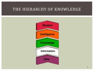
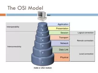
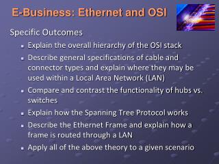
E-Business: Ethernet and OSI Specific Outcomes • Explain the overall hierarchy of the OSI stack • Describe general specifications of cable and connector types and explain where they may be used within a Local Area Network (LAN) • Compare and contrast the functionality of hubs vs. switches • Explain how the Spanning Tree Protocol works • Describe the Ethernet Frame and explain how a frame is routed through a LAN • Apply all of the above theory to a given scenario
Ethernet Dominance The “hoover” of networks • Ethernet is the dominant LAN technology • Over 95% of LAN ports are Ethernet • You need to know it well • Basic Ethernet switching is very simple • However, large Ethernet networks require more advanced knowledge
Ethernet History • Developed at Xerox Palo Alto Research Center in the 1970s • After a trip to the University of Hawaii’s Alohanet project. • Taken over by the IEEE • 802 LAN/MAN Standards Committee is in charge of LAN Standards. • 802.3 Working Group develops specific Ethernet standards. • 802.16 Busy refining WiMax standards. • Other working groups create other standards.
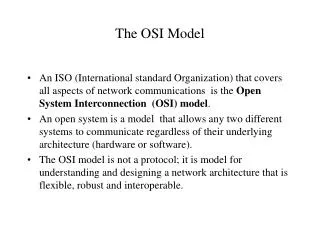
Ethernet Standards • Ethernet standards are LAN standards • LANs (and WANs) are single networks • Single networks are based on Layer 1 (physical) and Layer 2 (data link) standards • OSI dominates standards at these layers • Ethernet standards are OSI standards • Must be ratified by ISO, but this is a mere formality Layer 3 and above Layer 2 Layer 1
Baseband and Broadband Baseband Transmission Signal Transmitted Signal (Same) Source Transmission Medium Signal is injected directly into the transmission medium (wire, optical fiber) Inexpensive, so dominates wired LAN transmission technology
Baseband and Broadband Broadband Transmission Modulated Signal Radio Channel Source Radio Tuner Signal is first modulated to a higher frequency, then sent in a radio channel Expensive but needed for radio-based networks
Ethernet Physical Standards Physical Layer Standard Speed Maximum Run Length Medium UTP 10Base-T 10 Mbps* 100 meters 4-pair Category 3 or better *100Base-TX 100 Mbps 100 meters 4-pair Category 5 or better 1000Base-T 1,000 Mbps 100 meters 4-pair Category 5or better *With autosensing, 100Base-TX NICs and switches will slow to 10 Mbps for 10Base-T devices. Often called 10/100 Ethernet
Ethernet Physical Layer Standards Physical Layer Standard Speed Maximum Run Length Medium 1000Base-SX 1 Gbps 220 m 62.5/125 micron multimode, 850 nm, 160 MHz-km modal bandwidth (short wavelength) 1000Base-SX 1 Gbps 275 m 62.5/125 micron multimode, 850 nm, 200 MHz-km (short wavelength) 1000Base-SX 1 Gbps 500 m 50/125 micron multimode, 850 nm, 400 MHz-km (short wavelength) 1000Base-SX 1 Gbps 550 m 50/125 micron multimode, 850 nm; 500 MHz-km (short wavelength) Gigabit Ethernet, 850 nm, various core sizes and modal bandwidths Gigabit Ethernet usage is dominated by 1000Base-SX
Physical Layer Standard Speed Maximum Run Length Medium 1000Base-LX (long wavelength) 1 Gbps 550 m 62.5/125 micron multimode, 1300 nm 1000Base-LX (long wavelength) 1 Gbps 5 km 9/125 micron single-mode, 1300 nm Ethernet Physical Layer Standards Gigabit Ethernet, 1300 nm, multimode versus single-mode
Physical Layer Standard Speed Maximum Run Length Medium 10GBase-SR/SW 10 Gbps 65 m 62.5/125 micron multimode, 850 nm 10GBase-LX4 10 Gbps 300 m 62.5/125 micron multimode, 1300 Ethernet Physical Layer Standards 10 Gbps Ethernet, multimode S = 850 nm, L = 1300 nm R=LAN, W=WAN
Ethernet Physical Layer Standards Physical Layer Standard Speed Maximum Run Length Medium 10GBase-LR/LW 10 Gbps 10 km 9/125 micron single mode, 1300 nm. 10GBase-ER/EW 10 Gbps 40 km 9/125 micron single mode, 1550 nm. 10 Gbps Ethernet, for wide area networks L = 1300 nm, E = 1550 nm (E for extremely long wavelength) R = LAN, W = WAN
Ethernet Physical Layer Standards Fiber Standards
Ethernet Physical Layer Standards FTTH – (F)iber (T)o (T)he (H)ome
Ethernet Perspective • Access links to client stations today are dominated by at least 100Base-TX or 1000 Base T • Trunk links today are dominated by 1000Base-SX • Short trunk links, however, use UTP • Longer and faster trunk links use other fiber standards
Ethernet: Multiple Switches Original Signal Received Signal Regenerated Signal Switches regenerate signals before sending them out; This removes errors We need to carefully consider switch placementCentralised versus Decentralised wiring etc
Ethernet: Mutiple Switches (Datalink) Received Signal Original Signal Received Signal Received Signal Regenerated Signal Regenerated Signal Thanks to regeneration, signals can travel far acrossa series of switches
Ethernet: Mutiple Switches (Datalink) Received Signal Original Signal Received Signal Received Signal Regenerated Signal Regenerated Signal 62.5/125 Multimode Fiber UTP UTP 100Base-TX (100 m maximum) Physical Link 1000Base-SX (220 m maximum) Physical Link 100Base-TX (100 m maximum) Physical Link Each transmission line along the way has a distance limit.
Ethernet: Mutiple Switches (Datalink) Received Signal Original Signal Received Signal Received Signal Regenerated Signal Regenerated Signal 62.5/125 Multimode Fiber UTP UTP 100Base-TX (100 m maximum) Physical Link 1000Base-SX (220 m maximum) Physical Link 100Base-TX (100 m maximum) Physical Link Data Link Does Not Have a Maximum Distance (420 m distance spanned in this example)
802 Layering InternetLayer Data Link Layer Logical Link Control Layer Governs aspects of the communication Needed by all LANs, e.g., error correction. These functions not used in practice. Media Access Control Layer Governs aspects of the communication Specific to a particular LAN technology, e.g., Ethernet, 802.11 wireless LANs, etc. Physical Layer
802 Layering InternetLayer TCP/IP Internet Layer Standards (IP, ARP, etc.) Other Internet Layer Standards (IPX, etc.) Data Link Layer Logical Link Control Layer 802.2 Media Access Control Layer Ethernet 802.3 MAC Layer Standard Other MAC Standards (802.5, 802.11, etc.) … Physical Layer 10Base-T 1000 Base- SX Other Physical Layer Standards (802.11, etc.)
Ethernet Frame Field Preamble (7 Octets) 10101010 … Start-of-Frame Delimiter (1 Octet) 10101011 Note, last bit is a 1 symbolising end of synchronisation Destination MAC Address (48 bits) Source MAC Address (48 bits) No minimum length for 802.3 MAC layer however if data field <46 Octets, PAD field added by sender so that total length of data field =46 octets Length (2 Octets) Logical link control layer subheader 8 Octets (64bits) Purpose: Describe the type of packet contained within the Data Field ie (IP Packet or TCP packet etc) Data Field (Variable Length) LLC Subheader (8 Octets) Packet (Variable Length) PAD Field Used for error detection 4 Octet field. If error is detected, frame is simply discarded Frame Check Sequence (4 Octets)
Ethernet Frame 1/2 Field Preamble (7 Octets) 10101010 … Start-of-Frame Delimiter (1 Octet) 10101011 Computers use raw 48-bit MAC addresses; Humans use Hexadecimal notation (A1-23-9C-AB-33-53), Which is discussed Later. Destination MAC Address (48 bits) Source MAC Address (48 bits)
Ethernet Frame 2/2 May contain IP or IPX packet Field Length (2 Octets) Added if data field is less than 46 octets; Length set to make data field plus PAD field 46 octets; Not added if data field is greater than 46 octets long. Data Field (Variable Length) LLC Subheader (Usually 7 Octets) Packet (Variable Length) PAD Field If an error is found, the frame is discarded. Frame Check Sequence (4 Octets)
Multi Switch: Ethernet LAN The Situation: A1… Sends to E5… Switch 2 Port 5 on Switch 1 to Port 3 on Switch 2 Port 7 on Switch 2 to Port 4 on Switch 3 Switch 1 Switch 3 C3-2D-55-3B-A9-4F Switch 2, Port 5 B2-CD-13-5B-E4-65 Switch 1, Port 7 E5-BB-47-21-D3-56 Switch 3, Port 6 A1-44-D5-1F-AA-4C Switch 1, Port 2 D4-47-C4-B6-9F Switch 3, Port 2
Multi Switch: Ethernet LAN • Switching Table Switch 2 • PortStation • A1-44-D5-1F-AA-4C • 3 B2-CD-13-5B-E4-65 • C3-2D-55-3B-A9-4F • D4-47-55-C4-B6-9F • 7 E5-BB-47-21-D3-56 Switch 2 • Switching Table Switch 1 • PortStation • 2 A1-44-D5-1F-AA-4C • 7 B2-CD-13-5B-E4-65 • C3-2D-55-3B-A9-4F • 5 D4-47-55-C4-B6-9F • 5 E5-BB-47-21-D3-56 • Switching Table Switch 3 • PortStation • 4 A1-44-D5-1F-AA-4C • B2-CD-13-5B-E4-65 • 4 C3-2D-55-3B-A9-4F • 2 D4-47-55-C4-B6-9F • 6 E5-BB-47-21-D3-56 Switch 1 Switch 3 C3-2D-55-3B-A9-4F Switch 2, Port 5 B2-CD-13-5B-E4-65 Switch 1, Port 7 E5-BB-47-21-D3-56 Switch 3, Port 6 A1-44-D5-1F-AA-4C Switch 1, Port 2 D4-47-C4-B6-9F Switch 3, Port 2
Ethernet Switch Operation Ethernet Switch Switch Sends Frame Out One Port; If A Is Transmitting to C, Frame Only Goes Out C’s Port. C D A B
Hierarchical Ethernet LAN Single Possible Path Between Client PC 1 and Server Y Ethernet Switch A Ethernet Switch C Ethernet Switch B Ethernet Switch F Ethernet Switch D Ethernet Switch E Server X Server Y Client PC1
Ethernet Switch Operation • Only one possible path between stations • Therefore only one entry per MAC address in switching table • The switch can find the one address quickly, with little effort • This makes Ethernet switches inexpensive per frame handled • Low cost has ledto Ethernet’sLAN dominance PortStation 2 A1-44-D5-1F-AA-4C 7 B2-CD-13-5B-E4-65 5 E5-BB-47-21-D3-56
Hierarchical Ethernet LAN Core and Workgroup Switches Core Core Ethernet Switch A Core Ethernet Switch C Core Ethernet Switch B Workgroup Ethernet Switch F Workgroup Ethernet Switch D Workgroup Ethernet Switch E
Hierarchical Ethernet LAN • Workgroup switches connect to stations via access lines • Core switches higher in the hierarchy connect switches to other switches via trunk lines • The core is the collection of all core switches • Core switches need more capacity than workgroup switches because they have to handle the traffic of many conversations instead of just a few
Single Point of Failure in Switch Hierarchy Switch Fails Switch 2 No Communication No Communication C3-2D-55-3B-A9-4F Switch 1 Switch 3 B2-CD-13-5B-E4-65 D4-47-55-C4-B6-9F E5-BB-47-21-D3-56 A1-44-D5-1F-AA-4C
802.1D Spanning Tree Protocol Normal Operation Loop, but Spanning Tree Protocol Deactivates One Link Activated Switch 2 Activated Deactivated C3-2D-55-3B-A9-4F Switch 1 Switch 3 B2-CD-13-5B-E4-65 D4-47-55-C4-B6-9F E5-BB-47-21-D3-56 A1-44-D5-1F-AA-4C
802.1D Spanning Tree Protocol Switch 2 Fails Deactivated Switch 2 Deactivated Reactivated Switch 1 Switch 3 C3-2D-55-3B-A9-4F B2-CD-13-5B-E4-65 D4-47-55-C4-B6-9F A1-44-D5-1F-AA-4C E5-BB-47-21-D3-56
Server Broadcast Client C Client B Client A Server D Server E Virtual LAN (VLAN) in Ethernet Switch Servers Sometimes Broadcast; Goes To All Stations; Latency Results
Virtual LAN (VLAN) in Ethernet Switch With VLANs, Broadcasts Only Go To a Server’s VLAN Clients; Less Latency Server Broadcast No No Client C on VLAN1 Client B on VLAN2 Client A on VLAN1 Server D on VLAN2 Server E on VLAN1
Tagged Ethernet Frame (802.1Q) Tagged 802.3 MAC Frame Basic 802.3 MAC Frame Tag Control Information (2 Octets) Priority Level (0-7) (3 bits); VLAN ID (12 bits) 1 other bit Data Field (variable) Length (2 Octets) PAD (If Needed) Data Field (variable) Frame Check Sequence (4 Octets) PAD (If Needed) With VLAN’s switches do not use their normal switching tables but they use special VLAN Tables which associate VLAN ID numbers with one or more ports. Switches from different vendors can build their VLAN tables using standard VLAN ID numbers Frame Check Sequence (4 Octets)
Over-Provisioning Congestion and Latency Traffic Momentary Traffic Peak: Congestion and Latency Network Capacity Time
Over-Provisioning and Priority for Traffic Handling Traffic Overprovisioned Network Capacity Momentary Peak: No Congestion Time
Priority in Ethernet Priority in Ethernet Traffic Momentary Peak High-Priority Traffic Goes Low-Priority Waits Network Capacity Time
Switch Purchasing Considerations • Number and Speeds of Ports • Decide on the number of ports needed and the speed of each • Often can by a pre-built switch with the right configuration • Modular switches can be configured with appropriate port modules before or after purchase
Switch Purchasing Considerations • Switching Matrix Throughput • Aggregate throughput: total speed of switching matrix • Nonblocking capacity: switching matrix sufficient even if there is maximum input on all ports • Less than nonblocking capacity is workable • For core switches, at least 80% • For workgroup switches, at least 20%
Switch Purchasing Considerations 100 Mbps 1 Port 1 to Port 3 400 Mbps Aggregate Capacity to Be Nonblocking 100 Mbps 2 Any-to-Any Switching Matrix 100 Mbps 3 100 Mbps 4 100Base-TX Input Ports Input Queue(s) 100Base-TX Output Ports 1 2 3 4
Switch Purchasing Considerations • Store-and-Forward Versus Cut-Through Switching (Figure 4-18) • Store-and-forward Ethernet switches read whole frame before passing it on • Cut-through Ethernet switches read only some fields before passing it on • Perspective: Cut-through switches have less latency, but this is rarely important
Store and Forward Cut-through Cut-Through Based On MAC Destination Address (14 Octets) Preamble Start-of-Frame Delimiter Destination Address Source Address Cut-Through for Priority or VLANs (24 Octets) Store-and- Forward Processing Ends Here (Often Hundreds Of Bytes) Tag Fields if Present Length Data (and Perhaps PAD) Cyclical RedundancyCheck
Jitter • Jitter • Variability in latency from cell to cell. Makes voice sound jittery (Figure 4-19) High Jitter (High Variability in Latency) Low Jitter (Low Variability in Latency)
Switch Purchasing Decisions • Manageability • Manager controls many managed switches (Figure 4-20: Managed Switches) • Polling to collect data and problem diagnosis • Fixing switches remotely by changing their configurations • Providing network administrator with summary performance data