Download
1 / 38
380 likes | 569 Vues
Signals and Systems 1 Lecture 11 Dr. Ali. A. Jalali September 13, 2002. Signals and Systems 1. Lecture # 11 First TEST Review. EE 327 fall 2002. Signals and Systems. (Signals & Systems). Sequences. Signals. Systems. Electrocardiogram (ECG or EKG). EE 327 fall 2002.

E N D
Signals and Systems 1 Lecture 11 Dr. Ali. A. Jalali September 13, 2002
Signals and Systems 1 Lecture # 11 First TEST Review EE 327 fall 2002
Signals and Systems (Signals & Systems) Sequences Signals Systems Electrocardiogram (ECG or EKG) EE 327 fall 2002
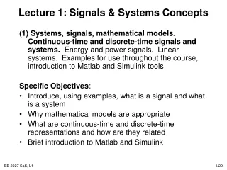
Signals and Systems • A signal is the physical form of a waveform, like a sound wave or a radio wave. • Time is often the independent variable for signal. • The independent variable can be 1-D or 2-D (space x, y in image), 3-D or N-D • A system is an object or channel that changes a signal that passes through it. • Amplifiers are systems that increase the amplitude of signals passing through them. • Attenuators are systems that decrease the amplitude of signals passing through them. EE 327 fall 2002
Signals and Systems • Signals • physical form of a waveform • e.g. a sound, electrical current, radio wave • Systems • a channel that changes a signal that passes through it • e.g. a telephone connection, a room, a vocal tract System Input Signal Output Signal EE 327 fall 2002
Signals: • Classification of Signals • Deterministic and Stochastic signals • Periodic and Aperiodic signals • Continuous time (CT) and Discrete time (DT) • Causal and anti-causal signals • Right and left sided signals • Bounded and unbounded signals • Even and odd signals EE 327 fall 2002
Building –block signals Unit impulse – definition • The unit impulse (t), is an important signal of CT systems. The Dirac delta function, is not a function in the ordinary sense. It is defined by the integral relation And is called a generalized function. • The unit impulse is not defined in terms of its values, but is defined by how it acts inside an integral when multiplied by a smooth function f(t). To see that the area of the unit impulse is 1, choose f(t) = 1 in the definition. We represent the unit impulse schematically as shown below; the number next to the impulse is its area. EE 327 fall 2002
Unit impulse- narrow pulse approximation • To obtain an intuitive feeling for the unit impulse, it is often helpful to imagine a set of rectangular pulses where each pulse has width and height 1/ so that its area is 1. The unit impulse is the quintessential tall and narrow pulse! EE 327 fall 2002
Unit impulse- intuiting the definition • To obtain some intuition about the meaning of the integral definition of the impulse, we will use a tall rectangular pulse of unit area as an approximation to the unit impulse. • As the rectangular pulse gets taller and narrower, EE 327 fall 2002
Unit Step Function • Integration of the unit impulse yields the unit step function which is defined as EE 327 fall 2002
%F1_7b Signal g(t) multiplied by a pulse functions EE 327 fall 2002
Successive integration of the unit impulse • Successive integration of the unit impulse yields a family of functions. • Later we will talk about the successive derivatives of (t), but these are too horrible to contemplate in the first lecture. EE 327 fall 2002
Building-block signals can be combined to make a rich population of signals • Unit steps and ramps can he combined to produce pulse signals. EE 327 fall 2002
Example: f(t) • Describe analytically the signals shown in Solution: Signal is (A/2)t at , turn on this signal at t = 0 and turn it off again at t = 2. This gives, A t 0 2 See page 9 of text for more examples. EE 327 fall 2002
Continuous Systems • Preview • A system is transforms input signals into output signals. • A continuous-time system receives an input signal x(t) and generates an output signals y(t). • y(t)=h(t)x(t) means the system h(t) acts on input signal x(t) to produce output signal y(t). • We concentrate on systems with one input and one output signal, i.e., Single-input, single output (SISO) systems. • Systems often denoted by block diagram. • Lines with arrows denote signals (not wires). Arrows show inputs and outputs Continuous-time System h(t) x ( t ) y ( t ) Output Input EE 327 fall 2002 Signals and Systems 1
Continuous Systems Example: Electric Network
Systems Classifications of systems: 1. Linear and nonlinear systems. 2. Time Invariant and time varying systems. 3. Causal, noncausal and anticausal systems. 4. Stable and unstable systems. 5. Memoryless systems and systems with memory. 6. Continuous and Discrete time systems. EE 327 fall 2002 Signals and Systems 1
Continuous Systems x ( t ) y ( t ) x ( t ) =C x ( t ) y ( t ) =C y ( t ) LS LS 1 1 1 1 1 1 Linearity: principle of homogeneity (c is real constant). principle of additively homogeneity and additively (Principle of superposition) x ( t ) y ( t ) LS 1 1 x ( t ) = x ( t )+ x ( t ) y ( t ) = y ( t )+ y ( t ) LS 1 2 1 2 x ( t ) y ( t ) LS 2 2 x ( t ) y ( t ) LS 1 1 y(t)=C1y1(t)+C2y2(t) X(t)=C1x1(t)+C2x2(t) LS x ( t ) y ( t ) LS 2 2 EE 327 fall 2002 Signals and Systems 1
Continuous Systems Linearity example: Let the response of a linear system at rest due to the system input be given by and let the response of the same system at rest due to another system input be Then the response of the same system at rest due to input given by Is simply obtained as: EE 327 fall 2002 Signals and Systems 1
Continuous Systems Time Invariance: x(t) y(t) x(t) y(t) LS t 1 t 1 3 y(t-T) x(t-T) x(t-T) y(t-T) LS T T t 1 4 Shifted input Shifted output For All value of t and T. t 1 EE 327 fall 2002 Signals and Systems 1
Continuous Systems Time invariant example: Let the response of a time-invariant linear system at rest due to be given by Then, the system response due to the shifted system input defined by Is EE 327 fall 2002 Signals and Systems 1
Differential Equation Model • Many physical systems are described by linear differential equations. • Reducing differential equations to algebraic equations • Homogeneous solution, exponential solution and natural frequencies. • Particular solution, system function and poles-zeros • Total solution, initial condition and steady-state • Conclusion
The Nth-order Differential Equation Model X(t) system input, Y(t) system output and our practical restriction order • The general linear constant-coefficient Nth-Order DE for SISO systems are: OR:
Initial Condition Solution of Differential Equation This is Characteristic Equation Can be written as: Or as factored form: Characteristic roots are: Where may be real or complex (conjugate pairs).
Example Solution 1- Find CE? The homogeneous differential equation is: Yielding the CE as: 2- CR? Using the quadratic formula, CR are: 3- Is this system stable? Both roots are negative real so the system is stable. 4- Algebraic form of IC response? 5- Constant IC solution? and Solving gives: and Thus
Unit Impulse Response The response of an LTI system to an input of unit impulse function is called the unit impulse response. Important:When determining the unit impulse response h(t) of an LTI system, it is necessary to make all initial conditions zero.(output due to input not energy stored in system) d x ( t ) = ( t ) y ( t ) = h ( t ) LTI EE 327 fall 2002 Signals and Systems 1
Convolution Integral • The convolution integral is one of the most important results used in the study of the response of linear systems. • If we know the unit impulse response h(t) for a linear system, by using the convolution integral we can compute the system output for any known input x(t). • In the following integration integral h(t) is the system’s unit impulse response. EE 327 fall 2002 Signals and Systems 1
Example for total response of system + Total response = ZIR + ZSR R y(t) C f(t) - IC response, Force response and Steady state response EE 327 fall 2002 Signals and Systems 1
f(t)= -2u(t+1)+3u(t)-u(t-2) EXAMPLE: f(t) 3u(t) 3 2 1 t -1 2 0 -u(t-2) -2 2u(t+1) f(t) 3u(t) 1 t 2 -u(t-2) -2 2u(t+1)
f(t)= -(t+4)u(t+4)+(t+2)u(t+2)+(t-2)u(t-2)-(t-4)u(t-4) EXAMPLE: f(t) 8 (t+2)u(t+2) 4 (t-2)u(t-2) 2 t -4 2 4 -2 0 -2 -(t-4)u(t-4) -(t+4)u(t+4) -4 f(t) 4 -4 0 -2 2 t -2
Sketch the following sequence? 4u(n-3)-2(n-6)u(n-6)+2(n-8)u(n-8) 4 0 1 9 2 3 4 5 6 7 8 4 0 1 9 2 3 4 5 6 7 8
Sketch the following sequence? 2(n+5)u(n+5)-3nu(n )+(n-10)u(n-10) Slop=2 Slop=1 (n-10)u(n-10) 2(n+5)u(n+5) 10 n 0 1 9 -5 2 3 4 5 6 7 8 10 After n = 10 the total slop is zero. Slop=-3 -3nu(n)
Graphical Solution EXAMPLE: * 1 1 t t -1 0 1 -1 0 1
-2<t<-1 1 -2 2 -1 0 1 -2+t t 1 -1 < t < 0 2 -2 -1 0 1 -2+t -1+t t
0 < t < 1 1 -2 2 -1 0 1 -2+t -1+t t 1 1 < t < 2 -2 2 -1 0 1 -2+t -1+t t
Convolution Plane EXAMPLE: * 1 1 t t -1 0 1 -1 0 1
Regions: 1 g h d f -1 1 -2 2 0 c e t a b -1
Integral arrangement: Integral y(t) Region t < -2 a -2 < t <-1 c d b -1 < t < 0 + + e g f 0 < t < 1 + + 1 < t < 2 h t > 2