Download
1 / 44
440 likes | 495 Vues
Explore the design drivers, concepts, heritage, assembly, and ongoing developments of the AXB boom unit for spacecraft. Features length adjustability, temperature ranges, and deployment mechanisms.

E N D
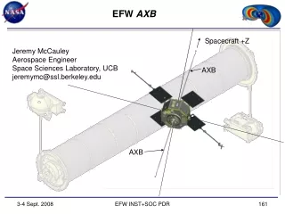
EFW AXB Spacecraft +Z Jeremy McCauley Aerospace Engineer Space Sciences Laboratory, UCB jeremymc@ssl.berkeley.edu AXB AXB EFW INST+SOC PDR
EFW AXBOverview • Design Drivers • Design Description • Concept • Heritage • Assembly Breakout • Thermal • ETU Integration and Testing (I&T) • MGSE Requirements • Ongoing Developments EFW INST+SOC PDR
EFW AXBDesign Drivers • Deploy spherical electric fields probes up to 6 meters with an E-Field sensor preamp at the end. • Length adjustable (longer only) on orbit with a resolution of +/- 0.5 cm • Interface to spacecraft to support deployable booms. • Meet straightness requirement (< 3” radial). • Provide relief for CTE mismatch between Gr/E Tube and SC body. • Provide a connector for test input to the sensor accessible during all integration phases. • Total Mass not to exceed 8.57 kg (Each AXB Unit to not exceed 3.64 kg; AXB Tube to not exceed 1.29 kg) • Interface Operational Temperature Range: -25 to +55C (TBR) • Interface Survival Temperature Range: -30 to +60C (TBR) EFW INST+SOC PDR
EFW AXBDesign Description: Concept Upper Boom Unit (+Z) Lower Boom Unit (-Z) • Axial Boom Unit (AXB) • Sensors Extended from SC on Stacers • Compact for Launch • Rigid after Deploy • Adjustable Length EFW INST+SOC PDR
EFW AXBDesign Description: Heritage • Heritage Unit • Primarily AXB from THEMIS, modified for length and to fit RBSP SC • Including Tube, Structure, Stacer, DAD design and springs • Similar to units on POLAR and FAST • Whip from Rockets • replaces THEMIS Whip Stacer • Direct Drive Unit from THEMIS SPB • Added Refinements • Direct Drive Unit on a Stacer • DAD Lock Wheel Assemblies • Sphere Caging Mechanism EFW INST+SOC PDR
EFW AXBDesign Description: Order of Deploy • Stowed Unit • Unpowered • Fully Restrained • Step 1: Whip Deploy • Frangibolt Actuated • Spring Powered +Z SC Axis • Step 2: Stacer Deploy • Frangibolt Release • Motor Driven (1.2 cm/s) • Length Adjustable EFW INST+SOC PDR
EFW AXBDesign Description: AXB Upper Boom Unit (+Z) Lower Boom Unit (-Z) • Structural Design • End Supported Tube with Aluminum End Fittings • Two (2) Identical Boom Units • Stationary Deploy Assy • Moving DAD • Stacer • Whip and Spherical Electric Fields Probe EFW INST+SOC PDR
EFW AXBDesign Description: Tube • Structural Design • End Supported Tube: Graphite Epoxy, M55 (Layup: 0, 45, 90, 45, 0 [quasi-isotropic]) • Fixed-Fixed First Frequency: 257 Hz • Tube Static Stress Margin: 10 • End Fittings: Al 6061-T6 • Lower Support includes a drumhead flexure design • Currently 89.1 lbf @ 52ºC dT • Static and Vibration testing as specified • Joint Epoxy: Hysol 9309NA • Bond Shear Stress Margin: 30.3 Flexure Tube End Fitting Flexure at dT=52ºC EFW INST+SOC PDR
EFW AXBDesign Description: Booms Stowed Configuration • Boom Design • Stationary Deploy Assy • Moving DAD • Stacer • Whip and Spherical Electric Fields Probe Whip Deploy Assy DAD Stacer Deployed Configuration EFW INST+SOC PDR
EFW AXBDesign Description: Booms Stowed Configuration • Stationary Deploy Assy • Sphere Caging Mechanism • Direct Drive Assembly • Roller Nozzle #1 Sphere Caging Mechanism Direct Drive Assy Roller Nozzle #1 Deployed Configuration EFW INST+SOC PDR
EFW AXBDesign Description: Booms Stowed Configuration • Sphere Caging Mechanism • Protect Spherical Electric Field Probe • Release Whip on Orbit • Frangibolt Actuator (Next Slide) • Top Opens • Cam Releases Arm • DAD Plunger with Kickoff Spring Starts Whip • AC Test Contact for Ground Operations • Torque Margin: 40.9 • Spring to Friction Drag • Green Tag Enable Plug/ Ground Test Plug DAD Plungers Frangibolt AC Test Contact Enable Plug Deployed Configuration EFW INST+SOC PDR
EFW AXBDesign Description: Frangibolt • Frangibolt • 500 lb Retention Force • For Launch Loads Only • Resettable • 25 W @ 28 Vdc • Actuation Time: < 10 s EFW INST+SOC PDR
EFW AXBDesign Description: Booms Frangibolt Slip Ring Motor Sense Switches Spool • Direct Drive Assembly • Stacer Frangibolt Release • Harness Spool: Max Capacity 9.2 meters 0.085” diameter cable • Motor Drive Mechanism: SPB motor (1000:1 gear ratio) • Sense Switches: Frangibolt Release, End of Travel and Turn Counter • Slip Ring • Length Resolution: 0.78 cm/click BOT, 0.53 cm/click EOT, 2.4 clicks/s • Torque Margin: 7.6 (Motor Torque to Torque to Retract Stacer) Harness EFW INST+SOC PDR
EFW AXBDesign Description: Booms • Roller Nozzle #1 • Centering of the Stacer • Resist SC Forces Rollers Rocker Arms EFW INST+SOC PDR
EFW AXBDesign Description: Booms • Moving DAD • Deployment Assist Device (DAD) with Kickoff Springs • Lock Wheel Assemblies • Increase Unseat Force from 6 lbs to 15 lbs axial from 1.6 to 4.5 lbs radial • Roller Nozzle #2 • Force Margin: 2.1 • DAD Springs to Friction Roller Nozzle #2 DAD Springs Lock Wheel Assy Stowed Configuration Deployed Configuration EFW INST+SOC PDR
EFW AXBDesign Description: Booms • Stacer • Helical Spring • Deployed Acts as a Rigid Tube • Spin Adjusted Resonance: 26.5 RPM • Force Margin: > 3 • Stacer Force to Friction Deployed Configuration Stacer EFW INST+SOC PDR
EFW AXBDesign Description: Booms Stowed Configuration • Whip and Spherical Electric Fields Probe • Hinge • Torque Margin: 3.6 • Hinge Spring to Friction • DAG 213 Coated • Whip Tube • FOS (Bending on Deploy): 2.0 • DAG 213 Coated • Sphere • Probe and Preamp Assy • DAG 213 Coated • Cannot Clean • All Three Isolated for Potential Control • Fundamental Frequency: 23.0 RPM • (> 4x SC Spin Rate Rigid) Sphere Internal View Preamp Hinge Whip Sphere Deployed Configuration EFW INST+SOC PDR
EFW AXBDesign Description: Thermal (TBC) • Thermally Coupled to the SC • Spherical Electric Fields Probe, Whip and Hinge: • Coated with DAG 213 • Stacer: • Mill Finish Elgiloy • Moving DAD: • Alodine (Gold) • Taped with Germanium Black Kapton • Electroless Nickel Plating with Teflon Impregnate • Stationary Deploy Assy: • Alodine (Gold) • Electroless Nickel Plating with Teflon Impregnate • End Supported Tube • M55 Graphite Epoxy • Aluminum End Fittings • Alodine (Gold) EFW INST+SOC PDR
EFW AXBDesign Description: I&T EFW INST+SOC PDR
EFW AXBDesign Description: I&T • ETU Flow: DDD Testing • Connectors need testing for Deep Dielectric Discharge (DDD) • Not reasonable on a part by part basis • Harness will be tested in unit, prior to Preamp installation Whip Hinge Whip Harness Sphere EFW INST+SOC PDR
EFW AXBDesign Description: I&T • ETU Flow: Deployments • Expected number of deployments on the instrument at launch: 4 • Length and Fundamental Frequency Test • Alignment and Runout Test • Thermal Vacuum Hot • Thermal Vacuum Cold • Deployments at Instrument and SC Level will be by means of Frangibolt simulators only EFW INST+SOC PDR
EFW AXBDesign Description: I&T • ETU Flow: Length and Fundamental Frequency Testing • Unit will be deployed horizontally on a g-negating track, then suspended vertically for fundamental frequency data. • Gravitational component will be subtracted from frequency. • Wire EOT switch test • Motor, Frangibolt current profile EFW INST+SOC PDR
EFW AXBDesign Description: I&T • ETU Flow: Alignment and Stiffness Testing • Requirement: 3 inches radial at Sphere • RSS Analysis of Stationary Deploy Assy and Moving DAD Tolerance Stackup: • 0.20 degree (0.8 inches) • Stacer Runout is not accounted for • Hinge, Whip and Sphere Runout is TBD • Unit will be deployed horizontally on a g-negating track, then lifted to floats for g-negated runout and stiffness measurements. (POLAR) EFW INST+SOC PDR
EFW AXBDesign Description: I&T • ETU Flow: Vibration Testing • Vibration (modal survey, sine, and random) to Qualification levels per 7417-9019 Section 5.4.5 at the Component level (IDPU, SPB, AXB) • Self-shock survival from boom deployments actuations shall be demonstrated at the component level (SPB and AXB) by at least 2 actuations (only the initial release generates a shock) • Post-vibration deployments during Thermal Vacuum testing EFW INST+SOC PDR
EFW AXBDesign Description: I&T • ETU Flow: Thermal Vacuum Testing • 6 operational cycles plus 1 survival cycle, per the requirements and limits indicated in 7417-9019 section 5.3.2 • Deployment tests will be performed at hot and cold levels • Whip and Caging Mechanism deployment testing performed at the subassembly level • Stacer deployment performed at the assembly level • Unit will be deployed horizontally on a g-negating track within the Thermal Vacuum Chamber • Preamplifiers will be separately tested. EFW INST+SOC PDR
EFW AXBDesign Description: MGSE • MGSE Required: • Whip Offload Fixture • Deployment testing of hinge, whip and sphere in air and at vacuum • Requires design and fabrication • Horizontal Deployment Track: • Deployment testing of Stacer in air and at vacuum • Requires adaptation of SWAVES Track for form factor • Runout Fixture: • G-negated runout measurements of the deployed antenna • Requires fabrication of float system and rotational fixtures • Vibe Fixture: • Vibration Testing of Boom Unit with Whip, Sphere and Caging Assembly • Requires design and fabrication • Shipping Container: • I&T Travel Protection • Requires adaptation of THEMIS or STEREO IMPACT Cases EFW INST+SOC PDR
EFW AXBOngoing Developments • Motor Driven Deployment of a Stacer • EM Deployment Testing Successful • Harnessing the Whip • EM Harness and Braid successfully built for Hinge Testing EFW INST+SOC PDR
EFW AXBDesign Description • Back up slides • Redundancy is Key…. EFW INST+SOC PDR
EFW AXBDesign Description EFW INST+SOC PDR
EFW AXBDesign Description EFW INST+SOC PDR
EFW AXBDesign Description EFW INST+SOC PDR
EFW AXBDesign Description EFW INST+SOC PDR
EFW AXBDesign Description EFW INST+SOC PDR
EFW AXBDesign Description EFW INST+SOC PDR
EFW AXBDesign Requirements • Mechanical Design Requirements • From 7417-9019 RBSP Environmental Specification, Rev. H • Quasi Static Limit Load: 25 g (5 kg to 25 kg) • Factors of Safety: See Chart • Provide a fundamental frequency of greater than 50 Hz (Stowed). EFW INST+SOC PDR
EFW AXBDesign Description: Materials • Materials and Properties Assumed • Metals, Yield Stress: • Brass 360, 49 kpsi • Aluminum, 2024-T8, 58 kpsi • Aluminum, 2117-T4, 24 kpsi • Aluminum, 5052-H32, 28 kpsi • Aluminum, 6061-T6, 40 kpsi • Beryllium Copper, #25 (C17200), 160 kpsi • Bronze C544, 35 kpsi • Copper (Oxygen-free, C10100), N/A • Elgiloy, Spring Temper • Steel, SS, 18-8, 70 kpsi • Steel, SS, 300 Series, 30 kpsi • Steel, SS, 400 Series, N/A • Tantalum per ASTM-B365-98, 65 kpsi (Ultimate) • Titanium, 6Al-4V, 120 kpsi EFW INST+SOC PDR
EFW AXBDesign Description: Materials • Materials and Properties Assumed • Composites: • Graphite Epoxy - Fiberite Hy-E 1034C or eq (M55) • Plastics: • Acrylic (Medium-high impact), 6kpsi • Black Delrin, 11 kpsi (Ultimate) • White Delrin, 11 kpsi (Ultimate) • Vespel SP3, 8 kpsi (Ultimate) • PEEK, 16 kpsi EFW INST+SOC PDR
EFW AXBDesign Description: Materials • Materials and Properties Assumed • Adhesives: • Hysol 9309NA, 4 kpsi (Tensile shear Strength) • Hysol 1C • Hysol 0151 • 3M EA1838 • 3M EA 2216 • Tapes: • Kapton Tape (acrylic adhesive) • Lubricants: • Braycote 601 –or— Braycote 601 EF • DAG 154 Paint EFW INST+SOC PDR
EFW AXBDesign Description: Materials • Coatings Used • Alodine per MIL-C-5541 CL 3 (Gold) • Black Anodize per MIL-A-8625 Type II, Class 2 • Hard Black Anodize per MIL-A-8625 Type III, Class 2 • Electroless Nickel Plating with Teflon Impregnate • Silver Plate per QQ-S-365 Type I, Grade A • Vapor Deposited Nickel • Braycote 601 –or— Braycote 601 EF • DAG154 Paint • DAG213 Paint EFW INST+SOC PDR
EFW AXBDesign Description: Stress Margins EFW INST+SOC PDR
EFW AXBDesign Description: Tube • Structural Design • End Supported Tube: Graphite Epoxy, M55 (Layup: 0, 45, 90, 45, 0 [quasi-isotropic]) • Fixed-Fixed First Frequency: 257 Hz EFW INST+SOC PDR
EFW AXBDesign Description: Booms EFW INST+SOC PDR
EFW AXBDesign Description: Booms Stowed Configuration • Whip and Spherical Electric Fields Probe • Hinge • Torque Margin: 3.6 • Hinge Spring to Friction • DAG 213 Coated • Whip Tube • FOS (Bending on Deploy): 2.0 • DAG 213 Coated • Sphere • Probe and Preamp Assy • DAG 213 Coated • Cannot Clean • All Three Isolated for Potential Control • Fundamental Frequency: 23.0 RPM • (> 4x SC Spin Rate Rigid) Preamp Hinge Whip Sphere Deployed Configuration EFW INST+SOC PDR
This page intentionally almost blank EFW INST+SOC PDR