“Low Power Operation”
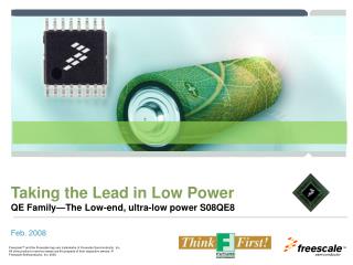
“Low Power Operation”. Texas Instruments University Programme Teaching Materials. Low Power Operation. Introduction. Low power operation is critical for long battery life of portable DSP based electronic devices: Pagers Mobile Phones Portable medical devices


“Low Power Operation”
E N D
Presentation Transcript
“Low Power Operation” Texas Instruments University Programme Teaching Materials
Introduction • Low power operation is critical for long battery life of portable DSP based electronic devices: • Pagers • Mobile Phones • Portable medical devices • There are several ways to minimise the power taken by the TMS320C5505, which will be discussed here.
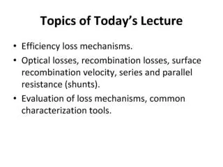
Objectives • To examine the factors that affect the power taken by a processor • To configure the Phase Lock Loop (PLL) on the TMS320C5505 USB Stick • To monitor the operating frequency using a digital frequency meter.
Digital System Waveforms Ideal Reality Power Consumption
Effect of Supply Voltage High Power Consumption High Voltage Low Voltage Lower Power Consumption
Reducing the Supply Voltage • Power is proportional to supply voltage squared V2. • V x 1 => Power x 1 • V x 2 => Power x 4 • V / 2 => Power / 4 • Reducing the supply voltage greatly reduces the power consumption.
Effect of Frequency Low Frequency Power Consumption High Frequency Power Consumption
Reducing the Frequency • Power consumption is proportional to frequency f • Reduce the frequency to reduce the power consumption.
Summary • Power consumption is proportional to voltage squared V2 • Power consumption is proportional to frequency f • For low power applications use: • minimum V • minimum f.
TMS320C5505 Clock Generator
Clock Generator Block Diagram • All devices use the System Clock (SYSCLK). • This sets the operating speed of the processor.
Why use a PLL? • The operating frequency of the device is adjustable in software • All high frequencies which are likely to cause electro-magnetic interference (EMI) are kept inside the device: • Low frequency outside (32676 Hz) • High frequency inside (100 MHz).
PLL Registers • The internal frequency of operation of the TMS320C5505 is controlled by the Phase Locked Loop (PLL) • There are 4 Clock Generator Control Registers used to configure the PLL: • CGCR1 • CGCR2 • CGCR3 • CGCR4.
CGCR1 • When PLL_PWRDN = 1, the PLL is powered down (off) • M contains the multiplier bits.
CGCR2 • CGCR2 contains the bypass and reference divider ratio (RDRATIO) fields.
CGCR3 • To set up the PLL, the INIT field must always contain 0x0806 • The Lock Status Monitor bit is used to test that the PLL is ready • During initialization it takes 4ms for the Lock Status Monitor to change from 0 to 1 (ready).
CGCR4 • Controls the output divide enable (OUTDIVEN) and the output divider (ODRATIO).
Power Management Features • There are several ways to reduce the power taken by the TMS320C5505:
Idle • The TMS320C55xx supports the assembly language instruction “IDLE” • This puts the processor to sleep • Wakeup is performed by an event such as an external interrupt.
Core Voltage Scaling • The supply to the core of the TMS320C5505 can be between 1.05V and 1.2V • Hardware can be designed to switch the supply to the core of the DSP from 1.2V (high processing speed) to 1.05V (lower processing speed).
PLL Frequency vs Core Volts • At 1.2V, the maximum SYSCLK is 100 MHz. At 1.05V the maximum SYSCLK reduces to 60 MHz • The TMS320C5505 USB stick uses a fixed core voltage and therefore does not support this feature.
Monitoring CLKOUT • The system clock SYSCLK is available on the CLKOUT pin of the TMS320C5505 USB Stick • It can be measured using a digital frequency meter.
Monitoring the XF LED • The XF LED on the TMS320C5505 USB Stick can be used to monitor the execution speed of the instructions.
PLL.c • To following C function has been added: pll_frequency_setup(); • This function takes one parameter, which is the required PLL frequency. • Supported values are 1, 2, 12, 40, 60, 75, 98 and 100. • For 12 MHz operation use: pll_frequency_setup(12);
Instruction Execution Times • When the PLL is running at 100 MHz: • 1 instruction takes 10 ns • When the PLL is running at 2 MHz: • 1 instruction takes 500 ns • The time to execute an instruction can be measured.
Display Power on XF LED • The loop takes the same time to execute, but the maximum value of counter1 depends on the PLL frequency • Use counter1 to control the brightness of XF LED • SYSCLK = 100 MHz • Maximum value counter1 is large • XF LED bright • SYSCLK = 2 MHz • Maximum value counter1 is small • XF LED dim.
Installing the Application • Copy the code given in Application 17 Low Power Operation to the workspace • Follow the steps previously given in Chapter 1 to set up the new project.
Microphone Setup USB to PC Microphone Headphones
Monitor the XF LED Frequency • When the TMS320C5505 is operating correctly, the frequency measured on the XF LED is 125 Hz.
Power Taken PLL = 100 MHz High power. LED bright.
Power Taken PLL = 2 MHz Low power. LED dim.
Change PLL Frequency • Modify the value passed to pll_frequency_setup() • Supported values are 1, 2, 12, 40, 60, 75, 98 and 100.
Lowest Frequency • What is the lowest PLL frequency that can be generated? • You will need to use both the Reference Divider and the Output Divider • Refer to the document in the References section.
Questions • How do voltage and frequency affect the power taken by a DSP? • What percentage of power is saved by switching the PLL from 100 MHz to 12 MHz? • What percentage of power is saved by switching the core voltage from 1.2V to 1.05V? • The TMS320C5505 supports several ways in which to reduce the power taken. What are they?
References • TMS320C5505 DSP System User’s Guide. SPRUFP0.