
Toroid Control System
E N D
Presentation Transcript
Toroid Control System Sheng Peng 02/08/2006
Outline • Requirement • External Interface • Schedule • Design Maturity • Wiring • Budget
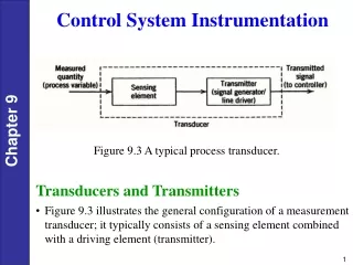
Requirement • There are four mechanical types of toroid • Three of them are the same to control • Toroid type 1 is in the GTL region • Toroid type 2 is in the region downbeam from L0 • Dump toroid • BCS toroid will be different, TBD • Fourteen toroids in total except BCS • Four toroids in injection line • Preamplifier is needed downstairs • Control system will interface with preamplifier to read signal, and give test signal to toroid
Requirement • Charge and Frequency Range: 2-1200pC • single pulse measurement at a frequency range of 1 Hz < f < 120 Hz • Resolution: 2 pC • Readout: 0 - 10Volts • Low Range Charge Accuracy: 2% RMS (linear) • High Range Charge Accuracy: 2.5% RMS (linear)
8Turns Pre-Amp ADC/ QADC Timing 1 Turn Trigger2 DAC Trigger1 Cycle start Send test signal Beam charge? Measure test signal Trigger1 Trigger2 External Interface
Control Interface At lease two signals come from pre-amp • Generate calibration charge • Read back calibration signal to calculate gain • Scan timing window to find the right delay • Read beam charge signal within right timing window
Schedule • Date needed: Dec, 2006 • Determine the QADC/ADC in Feb 2006 • Control’s prototype ready in ~July, 2006 • Hardware order date: TBD • Hardware delivery date: TBD • Installation: July ~ September, 2006 • Test period: one ~ two months • Toroid commissioning will be in Dec, 2006
Design Maturity • Toroid ESD 1.3-107(10/2005) is currently in use • The mechanical engineer is working on two proposal bids • The detailed interface will be defined after the winner is selected • Bergoz comes with preamplifier but ISA doesn’t, so SLAC might design the preamplifier if ISA wins
Wiring • Timing system is needed • Test input connector will be type N • Signal output connector will be TWINAX (or SMA as Bergoz proposed) • Wiring will be bakeable, radiation hard and qualify cable loss requirement • Cable is already planed for injection line, cable type is TBD • For injection line, one IOC may be enough • Control interface and software will be dependent on the selection of preamplifier
Budget • ~ $10,000/toroid • Control budget: • Estimate depends on design of preamplifier