Download
1 / 72
740 likes | 813 Vues
fabric manufacturing technology-1 fmt-1 knitting weaving

E N D
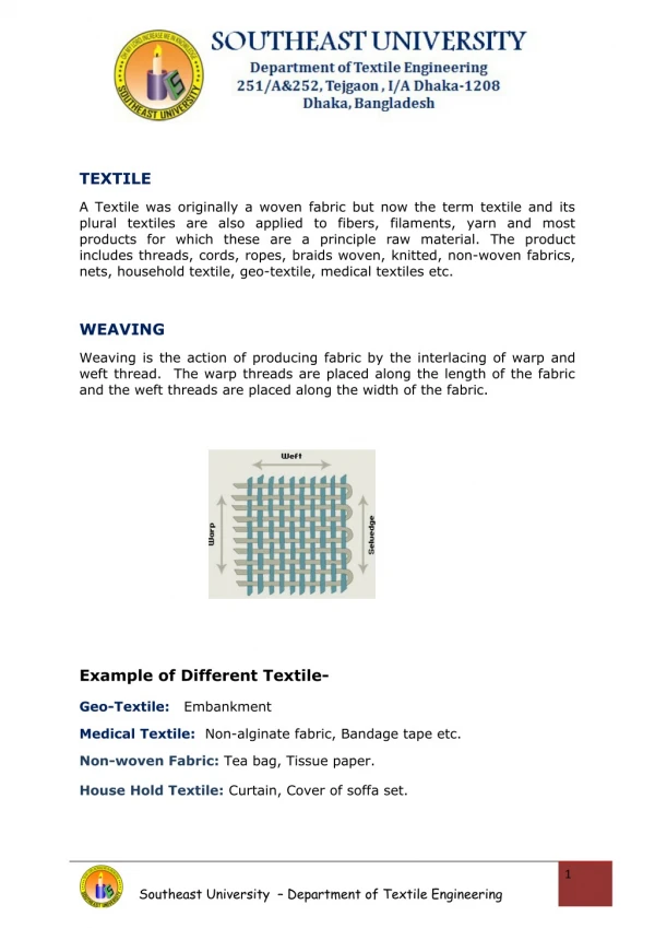
TEXTILE A Textile was originally a woven fabric but now the term textile and its plural textiles are also applied to fibers, filaments, yarn and most products for which these are a principle raw material. The product includes threads, cords, ropes, braids woven, knitted, non-woven fabrics, nets, household textile, geo-textile, medical textiles etc. WEAVING Weaving is the action of producing fabric by the interlacing of warp and weft thread. The warp threads are placed along the length of the fabric and the weft threads are placed along the width of the fabric. Example of Different Textile- Geo-Textile: Embankment Medical Textile: Non-alginate fabric, Bandage tape etc. Non-woven Fabric: Tea bag, Tissue paper. House Hold Textile: Curtain, Cover of soffa set. Southeast University – Department of Textile Engineering 1
FLOW CHART OF WEAVING Yarn (In the form of spinner’s package) Warp Preparation Weft Preparation Winding (cone, cheese) Winding (Cop, Pirn, Cone, Cheese) Warping (Pre beam/ Warper’s beam/ back beam) Weaving (Fabric) Sizing (weaver’s beam) Drafting, Drawing, Pinning Denting, Looming Weaving (Fabric) Three types of yarn package are mention bellow Cone Flange bobbin Cheese Southeast University – Department of Textile Engineering 2
TYPES OF FABRICS 1. Woven fabric (Shirt) 2. Knitted fabric (T-shirt) 3. Non-woven fabric (Tea pack) 4. Special fabric (Fire proof fabric, water proof fabric) OBJECTS OF YARN PREPARATION Yarn preparation is important to facilitate the next processes of weaving. The objects of yarn preparation are mentioned bellow: To remove yarn faults ( there are 23 types of yarn faults) To transfer the yarn from spinner’s package to a convenient form of packagewhich will facilitate weaving. To have desired length of yarn on a package. To clean the yarn for better appearance and performance. To make good quality fabric. To reduce labour cost. FAULTS TO BE REMOVED DURING YARN-PREPARATION 1. Thick place 2. Thin place 3. Slubs Place 4. Loose fibers Intentional 5. Count variation Unintentional Southeast University – Department of Textile Engineering 3
6. Foreign particles (seed, leaf, dust, bollworm, honeydew) 7. Neps QUALITY OF GOOD WARP The essential features of good warp is mentioned bellow- The yarn must be uniform, clean and free from knots as much as possible. The yarn must be sufficiently strong with withstand the stress and friction without end breakage. Knots should be a standard size and type. So that they can pass the heald eye, dropper, read easily. The warp must be uniformly sized and size coating should be thick enough to protect the yarn various function. The ends of warp must be parallel and each must be wound onto a weaver’s beam at an even and equal tension. All warp yarn should of same size in length. Southeast University – Department of Textile Engineering 4
PACKAGE TYPES OF PACKAGE Cone (for warp yarn) Cheese (for warp yarn) Spool (for silk, jute warp yarn) Flanged bobbin (for warp yarn) Cop (for jute weft) Pirn (for cotton weft) Spinner package TYPES OF PACKAGE WINDING There are three types of package winding available. 1. Parallel wound package 2. Near parallel wound package 3. Cross wound package 1. Parallel Wound Package Features a) Many yarn can be wound at a time. b) No need of traversing motion. c) Side withdrawal is possible. d) The density of yarn is more. e) No change of twist/inch. Southeast University – Department of Textile Engineering 5
f) For yarn unwinding separate mechanism is needed. g) Two side of the package needed flanged. 2. Near Parallel Wound Package Features a) No need flange here. b) Both side and overend withdrawal is possible. c) Twist/inch can be changed. d) Traversing motion is needed. 3. Cross-Wound Package Features a) Here no flange is required. b) Traversing mechanism is must. Twist/inch changes. d) Only overend withdrawal is possible. e) Yarn ballooning occurs during unwinding. f) This package is very stable. c) Southeast University – Department of Textile Engineering 6
PACKAGE DRIVING TYPES OF PACKAGE DRIVING There are three types of package driving system. A. surface contact driving (indirect system) B. direct driving at constant angular speed C. Direct Driving At Variable Angular Speed A. SURFACE CONTACT DRIVING (INDIRECT SYSTEM) In this system, the yarn package is placed with a surface contact of a drum. The drum is driven by a motor and some gear. When it rotates the package also rotate is reverse direction. Southeast University – Department of Textile Engineering 7
B. DIRECT DRIVING AT CONSTANT ANGULAR SPEED In this system, the package is placed on a spindle. The spindle is driven by a motor and some gears. So the package gets a constant angular speed. Here yarn take up rate is directly proportional to the package dia. C. DIRECT DRIVING AT VARIABLE ANGULAR SPEED In this system, yarn package is directly driven at a variable angular speed to give a constant yarn speed. Here the package speed is inversely proportional to the package radius, 1 I.e. Package speed Package radius Southeast University – Department of Textile Engineering 8
BALLOONING The appearance of the curved path of running yarn during unwinding or overend withdrawl from package under appropriate winding condition through a guide, placed above and in line with the axis of the package at an adequate distance from it, the yarn assumes the appearance of a balloon shape. This circumstance of assuming balloon shape of yarn is called ballooning. Southeast University – Department of Textile Engineering 9
FACTORS EFFECTING THE SHAPE AND SIZE OF BALLOON Package size Ballooning Yarn guide distance Ballooning Lift the package Ballooning Count of yarn Ballooning Air resistance Ballooning Unwinding rate. Ballooning YARN WITHDRAWAL OR UNWINDING The unwinding process of yarn from package is called yarn withdrawal. There are two types of yarn withdrawal system: 1. Side Withdrawal 2. Overend Withdrawal 1) Side Withdrawal The features of side withdrawl of yarn are given bellow; a) Package will rotate in side withdrawal. b) Yarn twist will be unchanged. c) No formation of balloon occurs. d) It is applied to flanged bobbin. e) The rate and speed of unwinding is slow. Southeast University – Department of Textile Engineering 10
2) Overend Withdrawal The features of overend withdrawl are given bellow; a) Package remains stationary during unwinding. b) Formation of balloon occurs. c) Twist/inch of yarn changed. d) Generally cop, pirn, cone, chess are packages used for overend withdrawl. e) The rate of unwinding is high. YARN GUIDE In winding and unwinding some small component control yarn path which is very necessary, yarn guide is used to perform this job. TYPES OF YARN GUIDE There are two types of yarn guide a) Yarn Guide For The Yarn Whose Ends Are Required For Threading; Southeast University – Department of Textile Engineering 11
For this type of yarn guide extra time is needed for threading. So speed of operation is decreased. The yarn which passes through this guide faces more friction. Like Ceramic, Tumpet, Bust b) Yarn Guide For The Yarn Whose Ends Are Not Required For Threading; Here threading is very easy. So the speed of the operation is high. Yarn passes through this guide faces less friction. Figure: Yarn Guide TENSION DEVICE During winding, we have to impart proper tension to yarn, so that we can get a stable and undamaged package. So we pass the yarn through a device called tension device. Types of Tension Device There are four types of tension device as follow; a) Capstan Tensioner. Southeast University – Department of Textile Engineering 12
b) Additive Tensioner. c) Combined Tensioner. d) Automatic Tensioner. A. CAPSTAN TENSIONER It is the simplest type of yarn tensioner. It works only by deflecting the yarn around fixed posts. This includes a capstan effect on yarn. It works by the following formula: Output Tension = Input Tension × eμθ or, T2 = T1 eμθ Where, T2 = Output tension. T1 = Input tension. e = Constant tension = 2.78 μ = Co-efficient of friction. θ = θ1+θ2+θ3 = Angle of lap. B. ADDITIVE TENSIONER This is also a simple technique of applying tension on yarn. In this device a dead weight or spring is used in the middle of the two surfaces in Southeast University – Department of Textile Engineering 13
contact and the force is applied to give suitable tension to the yarn. Hence the output tension is expressed by, T2 = T1 + 2μF Where, T1 = Input tension. T2 = Output tension. µ = Co-efficient of friction. F = Applied force. C. COMBINED TENSIONER It is the combined form of additive and capstan tensioner. The device permits the tension level to be raised to any desired level, but doesn’t permit a reduction of tension. Here output tension is expressed as follow: T2 = T1 + 2μF + T1 eμθ Where, T1 = Input tension. T2 = Output tension. µ = Co-efficient of friction. F = Applied force. θ = Angle of lap. D. AUTOMATIC TENSIONER It is a simple tensioner in which yarn tension is controlled automatically. It has a lever with spring loaded disc in one side and applied load in Southeast University – Department of Textile Engineering 14
another side. The device is designed in such a way that if applied tension is too high. The pressure on disc is reduced to bring the tension back to its proper level. EFFECT OF TENSIONING There are some effects of tension to the yarn or package: They are a) If tension is too high. Southeast University – Department of Textile Engineering 15
b) If tension is too low. c) If tension varies. b) If Tension is Too Low a) If Tension is Too High Loose package. Hard package. Unstable package. Breakage rate increases. Slough off. Elongation of yarn Shade variation. Weak the thin place. c) If Tension Varies Problem during unwinding. Package unstable. Irregularity among yarn. Auxiliary Function in Winding Creeling. Piecing. Doffing. CHOICE OF TENSIONING DEVICE It must be reliable. It must be easily threaded. It must neither introduce nor magnify tension variation. It must not change the twist of yarn. It must not be affected by wear. It must be easily adjustable. It must not be affected by the presence of oil and dirt. It must not encourage the collection of dirt and lint. It must be easy cleaning. The operating surface must be smooth. Southeast University – Department of Textile Engineering 16
It must be cheap. It must not cause any type of damage to yarn i.e. shade variation, elongation yarn breakage. WINDING PRECISION WINDING FEATURES Packages are wound with reciprocating traverse. Package contains more yarn. Low stability of package. Hard and more compact package. Low unwinding rate. The wound coils are arranged parallely or near parallely. FEATURES OF NON-PRECESSION WINDING Coils are cross wound. Package is of low density. Less amount of yarn is stored in package. High stability of package can be obtained. Flange is not necessary. Unwinding rate is very high. Difference between Precession and Non-Precession Winding Precession winding Non-Precession winding 1. The wound coil arranged parallel or near parallel. 1. The coil is cross wise wound. 2. The yarn density of the package is high. 2. The yarn density of a package is low. 3. Flanged bobbin may be used. 3. Not use of flanged. 4. The yarn package is hard and more compact. 4. The yarn package is soft and less compact. 5. Low stability of the package. 5. High stability of the package. 6. Winding angle is 90° or near 90° 6. Winding angle is less than 80° 7. The bobbin is wound with one or more threads 7. The bobbin is wound with single thread. Southeast University – Department of Textile Engineering 17
8. Yarn tension is comparatively high. 8. Yarn tension is comparatively low 9. Unwinding rate is low. 9. Unwinding rate is high. MATH-1 Calculate the time required to wind 500 lbs of 24 Ne cotton yarn on 15 drums, where the actual production per drum per minute is 560 yds. Given Production= 560yd/min/drum, 24 Ne, yarn= 500lb, time=? Solution 24 Ne means, 1 lb. of yarn contains = 24X840 yds. yarn 500 lbs. of yarn contains = (24X840X500) yds. yarn 560 yds. of yarn to wind in 1 drum needs =1 min 1 yd. “ “ “ (24X840X500) yd “ “ 15 drum = (24X840X500) / (560X15) min. =1200 min. =20 hr.(ans.) 15 drum “ =1/ (560X15) min. Math-2 Calculate the drum required to wind 900 lbs of 25 Ne cotton during the time 28 hrs, where the actual production per drum per minute is 600 yds Given, Production=600yd/min/drum 25 Ne, Yarn=900 lbs, time=28 hr., Find number of drum. Solution 25 Ne of yarns means, 1 lb of yarn contains 500 lb of yarn contains = 25X840 yd yarns. =(25X840X900) yd yarns. 600 yds. of yarn to wind in 1 min in = 1 drum 1 yd ’’ ’’ ’’ (60X28) min in = 1 / (600X60X28) drum. Southeast University – Department of Textile Engineering 18
(25X840X900) yds. ’’ (60X28) min = (25X840X900) / (600X28X600) drum = 18.75 drum = 19 drum (ans.) WARPIN Winding is a part of total number of ends of a warp in full width on to a back beam from cone or cheese is known as warping. OBJECTS OF WARPING To prepare a beam to make a fabric. To increase the wave ability of fabric. To make a convenient yarn sheet for sizing. To wound up required length of yarn onto a warp beam. To facilate the weaving of complex color pattern. To make reusable small packages REQUIREMENT OF WARPING During warping the following requirements should be fulfilled. 1. The tension of all wound end must be uniform and possibly constant throughout the withdrwal process. 2. Warping should not impair the physical and mechanical properties of yarn. 3. The surface of warping package must be cylindrical. 4. A pre-determined length of yarn should be wound on beam from every package. 5. The production rate of warping should be as high as possible. 6. If possible, yarn faults should be removed. TYPES OF WARPING Mainly there are two types of warping, a) Direct/ high speed warping b) Sectional warping. Southeast University – Department of Textile Engineering 19
Some Other Special Types of Warping Are Available a) Ball warping b) Chain warping c) Cross warping A. SECTIONAL WARPING Sectional warping is a process of preparing warp beam over two stages. In first stage yarns are wound in narrow tapes on a large drum. Then in the second stage the rewinding of the warp onto a beam is performed. This process is slow but suitable for complex color pattern. B. DIRECT/HIGH SPEED WARPING High speed warping is a process of preparing warp beam directly from yarn package. Here all the yarns are wound on a simple flange beam at a time. This process is suitable for single color pattern. FEATURES OF SECTIONAL WARPING Sectional warping is suitable for producing color fabrics with different pattern. Production is less in sectional warping. So it is a costly process. In sectional warping, tension cannot be kept uniform. Here tapered drum is used as drum. Hand weaving is necessary to produce sample fabric for bulk production. FEATURES OF HIGH SPEED WARPING High speed warping is suitable for producing fabric with same count and same color yarn. Higher amount of yarn is required here. The speed and production of a high speed warping is very high. Here simple flanged bobbin is used as beam. Southeast University – Department of Textile Engineering 20
Difference between Sectional Warping and High Speed Warping High Speed Warping Sectional Warping 1. Used to produce common fabric. 1. Used to produce fancy fabrics. 2. Production is high. 2. Production is low. 3. Large amount of yarn is required. 3. Small amount of yarn is required. 4. Weavers beam is produced after sizing. 4. Weavers beam is directly produced. 5. Cone and Cheese is used. 5. Flanged bobbin or drum is used. 6. The process is cheap. 6. The process is expensive. 7. High creel capacity. 7. Low creel capacity. 8. Most commonly use. 8. Rarely used. Control System in Warping Faults in Warping Tension control Off center warp Balloon control Reged or uneven warp Stop motion Cross end Yarn cleaner Snarl formation Hard/soft beam Southeast University – Department of Textile Engineering 21 End missing
Length control Surface speed control Proper yarn density Static electricity Traverse control Fly control Description of Different Control Systems in Warping 1. Tension Control: Tension should not be low or high during warping. Because due to lower tension package will be unstable, entangled and snarling will occur. Whereas high tension will cause yarn breakage. The tension should be just and uniform throughout the process. 2. Balloon Control: Balloon controlling is necessary so that the yarns does not entangled with one another. For this, yarn guides should be placed at right positions. 3. Stop Motion: The m/c should stop itself if any yarn breakage occurs at any point. So stop motion system is necessary to control. 4. Yarn Cleaner: Proper setting should be maintained to remove yarn faults. 5. Length Control: the Length of warp sheet should be controlled. It is done with a measuring roller in combination with a suitable counting device by stopping the device machine after winding pre-determined length of warp yarn onto the beam. 6. Surface Speed: The surface speed of beam should be controlled specially when a large change in warp diameter is involved. Southeast University – Department of Textile Engineering 22
7. Proper Yarn Density: In warp sheet the yarn ends/inch, means yarn density, is to be controlled. Because without proper yarn density the fabric will be uneven. 8. Static Electricity: It is specially required in case of man-made fibres. It is controlled to avoid yarn entanglement. It is done by: i. Chemical fiber finishes ii. Ionization of air. iii. Humidification of air. 9. Traverse Control: In sectional warping traverse rate of beam should be controlled. 10. Fly Control: In staple fibres lints, small trashes may cause problem by flying around the working area. So this fly should be controlled to have a pleasant working atmosphere. Description of Different Faults in Warping and Their Remedies: 1. Off Centre Warp: If beam or wraith is not set properly i.e. it is not centric due to carelessness this type of fault occurs. Remedy: Beam or wraith should be placed proper 2. Rigid or Uneven Warp Surface: This may occur if i. Yarn density [ends/inch] is very low. ii. Different counts of yarns is wound on beam/ iii. Yarn density is uneven. Remedy: yarn density and count should be maintained properly. 3. Cross Ends: If occurs due to faulty knotting after end breakage. (Joining broken end with wrong end) Remedy: Knotting and tension should be done carefully. 4. Snarl Formation: Snarl form due to over tension, highly twisted yarn and careless operation. Remedy: Tension should be kept proper and yarn twist should be as required. 5. Hard/Soft Beam: If during winding yarn on being yarn tension is low or high soft and hard beam forms. It may also occur due to uneven pressure on drum or beam. Southeast University – Department of Textile Engineering 23
Remedy: Tension and pressure should be maintained even. 6. End Missing: If yarn breakage occurs m/c should be stopped immediately. If such cannot be done the broken end of yarn cannot be found out. This is end missing problem. Remedy: Stop motion system should be very active and m/c should be stopped immediately after end breakage. 7. Haphazard Knotting: if various length of yarn is wound in creel packages then during beaming different end will finished in different time. So knotting would be in various places of the warp. This will haphazard knotting. Remedy: In creel packages same length of yarns should be present so that all yarn finish at a certain place of warp. 8. Length Variation: It may occur due to fault stop motion. It means if the stop motion system stops the m/c before winding required length of yarn on beam length variation occurs. Remedy: Stop motion should be checked carefully. Relation between Taper Angle and Amount of Yarn on a Beam Let, s = traverse length. L = Axis at length of warp on drum. d = empty beam dia. D = full beam dia. dm = = mean dia. X = tape distance α = taper angle v = volume of yarn stored on beam. Let, Southeast University – Department of Textile Engineering 24
s >x, so as to maintain stability. Π2 ) = (D+d) (D-d) = πL ( 4 V = - = ( - ) ( ) From figure, we can see that, D + d D - d 2 dm = , mean dia and = x tan α 2 So , V = π L dm (x tan α) or, V > π L dm (S tan α) if, x > s or, V < π L dm (S tan α) if, x < s So, V S tan α if α = 90° then V = s tan 90°= α So unlimited amount of yarns can be wound if flange stays perpendicular to beam barrel. Practically this is impossible. But this type of package permit’s to wind high amount of yarn. SIZING The method of applying a gelatinous film forming substance of starch on warp yarn before weaving is known as sizing. Object of Sizing To protect the yarn from abrasion with heald eye, back rest, reed etc. during weaving. To improve breaking strength of cellulosic yarn. To increase yarn smoothness. To reduce yarn hairness. To increase yarn elasticity and stiffness. To decrease yarn extensibility. To hinder generation of static electricity for synthetic and blended yarn. To increase yarn weight. Sizing Ingredients and Their Functions Some important size ingradients and their functions are mentioned below- Southeast University – Department of Textile Engineering 25
1. Adhesive 2. Lubricants or softeners 3. Antiseptic or antimildew agent 4. Deliquescent or Hygroscopic agent 5. Weighting agent 6. Anti-foaming agent 7. Tinting agent 8. Wetting agent 1. ADHESIVE Adhesives are mixed with water in granular form and heated to form a paste which ultimately becomes a viscous fluid. The followings do as adhesives in a size: Maize, corn, wheat, rice, potato starch. CMC (carboxyl methyl cellulose). PVA (poly vinyl alcohol). PVC (poly vinyl chloride). The functions of adhesives are as follows; To increase yarn strength. To reduce yarn hairiness. To increase elasticity and stiffness. To increase smoothness. 2. LUBRICANTS OR SOFTENERS Mineral waxex, vegetable waxes, animal fats; mineral oils, vegetable oils, tallow, Japan wax etc. are used as lubricants or softeners. Function Southeast University – Department of Textile Engineering 26
If softeners are not present in sizes the yarns will not be sufficiently extensible. Then the size would crack and particles would drop away from the yarn .And this, in turn, would create local stress concentration. 3. ANTISEPTIC OR ANTIMILDEW AGENT ZnCl₂, phenol, carboxylic acid, salicylic acid are used as antiseptic or antimildew agent. Function i. It helps to store the sized yarn protect it from bacteria and fungi. ii. It prevents the growth of mildew on yarn during storage. 4. DELIQUESCENT OR HYGROSCOPIC AGENT Hygroscopic agents present in size absorb moisture from air glycerin, CaCl₂ are some deliquescent agent. Function a) To prevent the brittleness of size. b) To absorb moisture from air. c) To prevent excessive dyeing of yarn. 5. WEIGHTING AGENT China clay, CaCO₃, Na₃,PO₄, France chal etc. are used as weighting agent. These are to be used specially for those fabrics that are to be solid in grey state. Function a) To increase the weight of yarn hen fabric. b) To impart fullness and feel to fabric. Southeast University – Department of Textile Engineering 27
6. ANTI-FOAMING AGENT Pyridine, benzene etc.as used as anti-foaming agent. Function: To prevent the formation foam 7. TINTING AGENT Blue is used as tinting agent. Function: a) To increase luster or brightness. b) To produce a pale color in dyeing. 8. WETTING AGENT Sulphanol A, soap, avirol, MgCl2 etc. are used as wetting agent in a size. Their drawbacks are their high and very stable foaming ability. Function: a) To ensure the uniform distribution of the sizing solution on yarn surface. b) Reduce surface tension of the liquor. c) Increase size absorbency. TECHNOLOGICAL CHANGES OCCURE DUE TO SIZING The following technological changes of a yarn/fabric occurs due to sizing – 1. INCREASE IN BREAKING STRENGTH 2. INCREASE ABRASION RESISTANCE 3. INCREASE IN STIFFNESS 4. INCREASE IN ELASTICITY 5. INCREASE IN FRICTIONAL RISISTANCE 6. INCREASE IN YARN DIAMETER 7. DECREASE IN YARN HAIRINESS 8. DECREASE IN STATIC ELECTRICITY FORMATION DESCRIPTION 1. INCREASE IN BREAKING STRENGTH Southeast University – Department of Textile Engineering 28
During sizing adhesive materials create bonds between fibers to fiber which, as a result, increase the breaking strength of the yarn. It increases 20-40% breaking strength of the fiber. 2. INCREASE ABRASION RESISTANCE After sizing the gap between fibers are filled with size due to the coating of size on the outer surface of the yarn. So their resistance against abrasion is increased. 3. INCREASE IN STIFFNESS After sizing flexibility or pliability of a yarn is decreased and stiffness is increased. 4. INCREASE IN ELASTICITY As extensibility of the sized yarn decreases, more force is to be applied to extend the yarn. This is means, elasticity of the yarn increases. 5. INCREASE IN FRICTIONAL RISISTANCE Sizing produces smooth yarn surface and so less friction occurs. Again size coating increases the frictional resistance of yarn 6. INCREASE IN YARN DIAMETER Due to coating of size ingredients the yarn diameter increase but yarn’s apparent diameter is decreased. 7. DECREASE IN YARN HAIRINESS By sizing protruding hairs of yarn fix with yarn and so yarn hairiness decreases mentionably. 8. DECREASE IN STATIC ELECTRICITY FORMATION Size materials contain hygroscopic agent and water which hinder the formation of static change on yarn surface. Again due to mass frictional resistance the formation of static electricity becomes less. SIZE TAKE-UP PERCENTAGE Wt. of size material on yarn × 100% Southeast University – Department of Textile Engineering 29
Size take up % = Wt. of unsized yarn Size Take up Percentage Depends on the Following Factors Twist S.T Yarn count S.T Viscosity of size material S.T speed of yarn passing through m/c S.T Pressure of squeezing roller. S.T Amorphousness of fiber in yarn. S.T Flexibility of yarn S.T Nature of adhesive. S.T Time and Temperature. S.T SIZE CALCULATION MATH-1: A beam of wt. 260 lbs. contains 4000 sized warp of 1200 yds length. It the unsized yarn count is 30 Ne and empty beam wt. 50 lbs., then calculate - i. Wt. of size on yarn. ii. Count of sized yarn. iii. Size take-up percentage. Soln: 4000×1200 Weight of unsized yarn = yds 840×30 = 190.47 lb. Southeast University – Department of Textile Engineering 30
Wt. of sized Yarn = (260 – 50) lbs. = 210 lbs. Wt. of size material = (210 - 190.47) lbs = 19.53 lb. (Ans) 4000×1200 Wt. of sized yarn = yds. 840×C 4800000 or, 210 = 840×C 4800000 or, C = = 27.21 = 27 Ne (Ans) 840 × 210 Size take up percentage (%) = (wt. of size material on yarn / wt. of unsized Yarn) x 100 % = 19.53/190.47 x 100 % = 10.25 % (Ans) LOOM The loom is the contact point of the whole process of cloth production, ginning, opening, carding, spinning, winding, warping, sizing and beaming are done before weaving. A loom cannot be said a machine but it is a Southeast University – Department of Textile Engineering 31
device which is used to produce woven fabric. Looms are generally driven either by line shaft or by individual motors fitted with it. Weaving Mechanism / Basic Principle of Weaving Weaving is the process of interlacement between the warp and weft in fabric according to a design of fabric. Basic principle or weaving mechanism is: The yarn from the weavers beam passes round the back rest and comes forward through the drop wire of the warp stop motion to the heald eye of heald shaft which is responsible for the purpose of shade formation. It then passes through the dent of reed which holds the thread at uniform spacing and it is also performed the beating up the weft thread that has been left in the triangle warp sheet form by the two warp sheet and reed. In this way, weft yarn is meshes with last pick of fabric or cloth. Temple holds the cloth firm at the feed position and assist in the formation of a uniform fabric width. Then fabric passes over the front rest, take up roller, pressure roller and finally wind on to the cloth roller. DRIVING MOTION Southeast University – Department of Textile Engineering 32
It is seen that the figure that, two tappet mounted with the one bottom shaft and it passed the treadle lever by treadle bowl to down direction. There is a fulcrum at the end of treadle lever and another end of lever is joined with heald shaft by yarn. Top roller acts as intermediate of two rope of heald shaft from which rope passes over the top roller. When shedding cam or tappet pressed on the treadle lever by treadle bowl, then one heald shaft is down while another is up and shedding is formed. Such way, 2nd shedding tappet reverses full motion i.e. upper heald shaft is down and down heald shaft is up. The mechanism of a power loom receives their motion from shaft that traverses from side to side in the loom and is driver from another. Their relative speeds are of importance since they give the mechanism that they drive. The crank shaft being driven by the motor moves one revolution per picks. The motion of the teeth of the gear wheels connecting this shaft to the bottom shaft is always 2:1, so that the bottom shaft will move one revolution in ever two picks. Southeast University – Department of Textile Engineering 33
CLASSIFICATION Loom Hand Loom Power Loom Modern or Shuttle less Loom Automatic Power Loom Ordinary Power Loom Modern or Shuttle less Loom Ordinary Motor Hand Loom 1. Common Motor. 2. Individual motor. 1. Primitive or Vertical loom. 1. Projectile Loom. 2. Rapier Loom. 3. Air jet Loom. 2. Pit loom (a) Throw shuttle loom. 4. Multiphase. (b) Fly shuttle loom. 3. Frame loom (a) Throw shuttle loom. (b) Fly shuttle loom. 4. Chitttaranjan loom. 5. Hattersley loom Southeast University – Department of Textile Engineering 34
LOOM MOTION Loom Primary Motion Secondary Motion Tertiary Motion Primary motion Secondary Motion 1. Take up (a) Positive (b) Negative. 1. Shedding: (a) Tappet (b) Dobby. (c) Jacquard. 2. Picking: (a) Over pick (b) Under pick. (c) Modern pick. 3. Beating: (a) Single (b) Multiple (c)Variable. 2. Let off (a) Positive (b) Negative. (5 wheel, 7 wheel) Tertiary Motion 1. Warp stop motion 2. Weft stop motion (Centre, side) 3. Reed stop motion (Loose, fast) 4. Temple motion (Roller, reed) 5. Weft replenish Southeast University – Department of Textile Engineering 35
1. Primary Motion In order to interlace warp and weft thread to produce fabric on any type of weaving machine 3 primary motion is necessary: I) Shedding: It is the process of separating the warp thread into two layers to form a tunnel called shed (through which shuttle carrying weft passes) is known as shedding. During shedding some yarns are raised up and some are depressed down create a tunnel. II) Picking: The method of passing the weft threads which traverse across the fabric through shed is called picking. The inserted weft is called a pick. III) Beating: It is the process of pushing the pick into the already woven fabric at a point known as fell of the cloth .By pressure of wraith to jointed feed side of the cloth is called beating. 2. Secondary Motion I) Take up motion: The motion which with draw (wound up) fabric from the weaving area at a constant rate and thus give required pick spacings and winds the fabric on to a roller is called cloth control or Take up motion. Positive Take up motions is mechanically driven. Negative Take up motions is spring drive. II) Let off motion: The motion which deliver warp to the weaving at the required rate and at a suitable constant tension by unwinding it from a flanged known as weavers beam is called let off motion. Southeast University – Department of Textile Engineering 36
3. Tertiary Motion Tertiary motion is not must for fabric production but it is used for higher production. 1. Warp Stop Motion: Machine will be stopped electrically or mechanically. 2. Weft stop motion: It may be two types- (a) Side weft motion & (b) Centre weft motion. 3. Reed stop motion: Two types- (a) Fast reed motion. (b) Loose reed motion. SHEDDING Dividation of warp threads into two parts for insertion of weft threads is called shed and the mechanism of shed is called shedding, it is the first primary motion of weaving Types of Shed 1. Bottom close shed 2. Centre close shed 3. semi-open shed 4. Open shed Southeast University – Department of Textile Engineering 37
Primitive Loom /Vertical Loom Warp yarn is taken in a roller instead of beam and hanged in a wall and shed is produced by a piece of wood. In this loom the vertical frame is used to hold the warp in stretched condition. Weft is passed through the shed by hand. Beating is done by the pressure of hand. Take off action was done in a separate roller by hand. Let off was also by hand. One weaving cycle Picking Beating Shedding Primary motion Throw Shuttle Pit Loom In this loom, the frame was laid on a pit. Shedding was obtained by giving the pressure to the treadle levers suited inside of the pit by feet. The weaver throws the shuttle across the width of the cloth by one hand and catches it by another hand. Chittarajan Loom It is constructed by iron and wood. The principle characteristics of this loom is – The two wheels upon a shaft connect the sley two ends with the help of two levers. Regulating the sweep of sley and force of beat up allowing less strain to weaver and uniform force to beat up. The positive take up motion by the five wheels to regulate the picks per inch. The alternation of picks per inch is positive by changing the wheel to take up motion. Negative let off motion with chain, lever and dead weights has been adopted in this loom to ensure uniform let off warp cloth is taken up by positive means. Southeast University – Department of Textile Engineering 38
Shedding and picking motion work in the same manner as in the fly shuttle loom but the loom speed is greater than hand loom. Shedding motions are generated manually but secondary motions like let off and take up are done automatically. So this loom may be called semi-automatic loom. Southeast University – Department of Textile Engineering 39
JUTE LOOM Hessian Loom Used for comparatively fine fabrics Larger loom width 2 heald shaft, one yarn/ heald eye Finer reed Two tappet and tappet are on bottom shaft Small pinion on pin roller Suitable for plain weave(1 up1 down) Yarn count—7.5 lb/spindle Backrest attach with frame Sacking Loom Comparatively coarse fabric Loom width is less 3 heald shaft,3 yarn/heald eye Coarse reed Larger pin on pin roller Suitable for twill weave(2 up,1 down) Yarn count (8-10), around 8.5 lb/spindle Separate back rest Tappets are on counter shaft. Advantages of Fly Shuttle Loom/ Reason for Choice of Fly Shuttle Loom Higher m/c speed or weaving speed(60-80rpm) Maximum speed of Pit loom-60 rpm Hand through Pit loom-20 rpm Vertical loom-1 ppm No. of heald shaft is higher In fly shuttle loom, higher width fabric is possible In Pit loom, only narrow width fabric can be woven Solid and compact structure with minimum vibration Fly shuttle loom- more compact and solid structure -minimum vibration Southeast University – Department of Textile Engineering 40
-less space Pit loom-higher vibration -more space Flanged weavers beam provided better selvedge Fly shuttle loom-wooden flanged weavers beam ensure better selvedge Pit loom- without flanged weavers loom Adjustable back rest to suit quality fabric Pit loom- fixed back rest 22 Let-off with lever arrangement -Uniform let-off of yarn is possible. Adjustable sweep of sley –suit quality fabric. Pit loom-over hanging sley assembly -sweep of sley is not adjustable. Fly shuttle loom-sley assembly is supported by sley sword More freely operated treadles. More cloth on cloth roller is possible. Positive take-up can be fitted. Free picker Dobby and jacquard can be fitted. Suitable for both fine and coarse fabric. Difference between Hand Loom and Power Loom Hand Loom Power Loom 1. Operating system is manual. 2. Shedding is done by paddle and Picking, Beating is done by hand. 3. Less production. 1. Operating by electric power. 2. Shedding and Picking is done automatically. 3. High production. 4. Slow running speed. 4. High running speed. 5. Check and striped fabrics are produced. 5. One color fabrics is produced. Southeast University – Department of Textile Engineering 41
Difference between Hesian and Sacking Loom Hesian Loom Sacking Loom 1. One up one down plain weave. 2. It has two heald shafts. 1. Two up one down twill weave. 2. It has 3 eald shafts. 3. No of tappet 2. 3. No of tappet 3 4. No auxiliary shaft. 4. Need of auxiliary shaft due to more 2 tappet is called counter shaft. 5. Two yarns are passed through a heald eye. 6. More spacing between warp yarns. 7. Coarser thread is used. 5. A single yarn is passed through a heald eye. 6. Less spacing between warp yarns. 7. Finer thread is used. New condensed notation (DIN 61 101) 10 01 00 0101 Construction 10 Plain 20 Twill 30 Satin Lifting pattern of the first warp yarn No. of adjacent warp yarns with identical lifting pattern Move number Southeast University – Department of Textile Engineering 42
DEFINITION Knitting is the method of creating fabric by transforming continuous strands of yarn into a series of interlocking loops, each row of such loop hanging by the one immediately preceding it. The basic element of knit fabric structure is the loop intermeshed with the loops adjacent to it on both side and above and below it. Fig: knitting structure TERMS Kink of Yarn:Per loop from a single yarn. Knitted Loop: two loops intermeshed. Knitted Stitch: Three loops intermeshed. Top Arc: Loop Head Bottom Half Arc Leg/ Side Limber Needle Loop Sinker Loop Close Loop Open Loop Southeast University – Department of Textile Engineering 43
Wale: Vertical column of needle loop. Course: Horizontal row of needle loop. Stitch Density: Wales per Inch × Course per Inch. Stitch length: Needle loop + Sinker loop Extended sinker loop Face loop Back loop United Needle Needle: Independent Needle Southeast University – Department of Textile Engineering 44
Knitting M/C: there are three types of knitting M/C – 1. Warp knitting: Gives vertical movement of yarn. 2. Weft knitting: Gives horizontal movement of yarn. 3. Other loop forming and combined M/C: Tri-axial. Needle Carrier: Which carries needle. Number of Feed System: The number of feeder by course. Working Diameter: In circular knitting m/c, the distance from one needle exact to the other needle is known as working dia. Working Width: In flat knitting m/c, the distance from first needle to the last needle is known as working width. Gauge: Number of needle per inch. Pitch: The distance the center from one needle to the center of another needle is known as pitch. There Are Three Types Of Knitted Fabric Selvage fabric Southeast University – Department of Textile Engineering 45
Cut edge fabric Tubular fabric Over lap Open lap Under lap Close lap O = over lap U = under lap DIAL Dial is the upper steel needle bed used in double knit machines. Into the grooves of the dial, the needles are mounted horizontally and are allowed to move radially in and out by their dial cams. The number of grooves per unit space conforms to the cylinder gauge in most of the cases. Fig: Dial CYLINDER Southeast University – Department of Textile Engineering 46
The cylinder is a steel circular bed having grooves/tricks/cuts on its outer periphery into which the needles are mounted. With reference to the tricks, the needles move vertically up and down by their butt being in contact with the cam track. The number of tricks per inch i.e., number of needles per inch decides the gauge of the machine. Machines are built as low as 4 NPI to as high as 32 NPI. Based on the machine gauge, the fineness of the yarn to be knitted can be varied. The diameter of the cylinder also varied based on the type and width of the fabric and a maximum of 75 cm diameter machines are available. Fig: Cylinder FEEDERS/STRIPPERS Feeders are the yarn guides placed close to the needles to the full circumference of the knitting zone. The feeders feed the yarn into the needle hooks and control the needle latches in their open position while the needle attain their clearing position. They consist of a yarn guiding hole and a bevel edge to guard the latches of the approaching needles. They are slightly curved to the corresponding curvature of the needle bed. Feeders may have two holes also for the purpose of plating. Yarn feeders can be divided into “positive” or “negative” types depending on the possibility of controlling the yarn feeding speed and uniformity. Southeast University – Department of Textile Engineering 47
Fig: Feeders/Stripers The feeder brackets can be adjusted to set their distance from the needle and to ensure yarn feed into needle hooks. Stripers are the feeders designed to deliver two or more yarns individually to the same feed. They can be considered as moving guide replacing the holes of fixed guides. In a two color stripe, two different colored yarns are supplied by two stripper fingers and their engagement is controlled by an endless control chain which governs the guide change at the appropriate feeds. At each revolution, a counter may select the movement of all the striper chains. The stripes are used on both single and double bed machines. Circular Knitting MACHINE DESCRIPTION Southeast University – Department of Textile Engineering 48
Frame The circular knitting machine consists three major sections viz., yarn supply, knitting elements and fabric take-down. The Fig. 2.3 shows the machine frame, indicating its various parts. The knitting elements such as needles, sinkers, cylinder, cams and feeders are supported at the center called as knitting zone. Yarn packages are mounted at the overhead creels and yarns are fed to knitting zone through yarn guides, stop motions and feeders. The knitted fabric goes down inside the cylinder towards the centre of the machine, drawn into the take down device and finally collected on a roll winding mechanism. A fabric spreader gradually converts the tubular fabric into a double layer folded fabric by preventing the formation of pleats or creases. At the knitting zone, single knit plain machines are fitted with a cylinder and sinker ring, whereas the double knit machines have cylinder and dial. 1. Legs 2. Cylinder 3. Dial 4. Needle 5. Cam Parts 6. Feeder guide 7. Cam 8. Supply Package 9. Creel 10. Top Stop Motion 11. Anti Snarl Device Drive The drive to the knitting machine is simple and direct. The motor imparts rotary motion to the rotating needle beds, such as cylinder and dial and also to the take-down and cloth winding mechanisms. MECHANICAL PRINCIPAL OF KNITTING TECHNOLOGY Basic Elements of Knitting Southeast University – Department of Textile Engineering 49
1. Needle 2. Sinker 3. Cam 1.NEEDLE: There are various types of needle are available in market which can be divided in the following group. a. Spring Bearded Needle b. Latch Needle c. Compound Needle SPRING BEARDED NEEDLE Stem: The stem around which the needle loop is formed. Beard: To create new loop. Eye/groove: To receive the beard. Shank or butt: To support and give strength to the needle. And control the movement of needle. Tip: To receive the latch spoon. Head: To open and close the latch. Stem: It around which the needle loop is formed. Southeast University – Department of Textile Engineering 50