Download
1 / 56
590 likes | 1.01k Vues
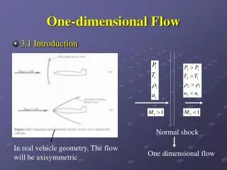
One Dimensional Flow with Heat Addition. P M V Subbarao Professor Mechanical Engineering Department I I T Delhi. A Gas Dynamic Model for Cross Country Gas Pipe Lines…. Ideal Flow in A Constant Area Duct with heat Transfer. Mach equation gives. Mach equation in Momentum equation gives.

E N D
One Dimensional Flow with Heat Addition P M V Subbarao Professor Mechanical Engineering Department I I T Delhi A Gas Dynamic Model for Cross Country Gas Pipe Lines…..
Mach equation gives Mach equation in Momentum equation gives Mach equation in Energy equation gives
Integrating from point 1 to point 2: In subsonic flow, heat addition increases the Mach Number. In supersonic flow, heat addition decreases the Mach Number. Addition of heat leads the flow to move towards M=1. Removal of heat leads the flow to move away from M=1. Therefore T0 will be maximum when M=1.
Variation of Stagnation Temperature with Mach Number Heat Removal Heat Removal T0 Heat Addition Heat Addition M=1 M
Total Heat Addition or Removal Total heat transfer per unit mass flow rate
Relation Between M1 and M2 Adiabatic ideal flow:
Similarly, for an ideal flow with heat addition and for an ideal flow with heat removal
Adiabatic Heat Removal Relation Between M1 and M2 Heat Addition M2 M1
Entropy Change : Heat Addition or Removal Integration from 1 to 2:
Adiabatic Heat Removal Heat Addition M1
Maximum End Condition • If heat is added to the flow, the Mach number tends towards one. • If heat is removed from the flow, the Mach number tends away from one. • All the properties of the flow can be conveniently written in terms of conditions that exist when M2 = 1.
Variation of Normalized Properties Normalized Values M1
Temperature Entropy Relation • Traditionally, heat addition or removal is characterized through relative temperature – entropy variations. • Entropy signifies the quality of heat transfer process. • An explicit relation between entropy and temperature is very useful in evaluating the heat transfer process. On integration till maximum end point.
The pressure ratio equation gives: Substitute M2 in equation for temperature ratio :
The roots of the equation are: This allows the variation of temperature ratio with change in entropy to be found for any value of g.
Rayliegh Line One dimensional ideal flow with heat transfer is called as Rayliegh flow.
Maximum Entropy and Maximum Temperature Points • Entropy will be maximum when M=1. • Heat addition moves the Mach number towards 1 and vice versa. • The point of maximum temperature occurs not at M=1. • This value can be found by differentiating temperature ratio equation.
M corresponding to Tmax: Tmax occurs at M<1 and
Variable Area with Heat Transfer Conservation of mass for steady flow: Conservation of momentum for ideal steady flow:
Conservation of energy for ideal steady flow: Ideal Gas law: Combining momentum and gas law:
For heat addition, M=1,dA will be positive. For heat removal, M=1,dA will be negative.
One Dimensional Flow with Heat Transfer & Friction P M V Subbarao Associate Professor Mechanical Engineering Department I I T Delhi A Gas Dynamic Model for Gas Cooled High Heat Release Systems…..
Governing Equations Nonreacting, no bodyforces, viscous work negligible Conservation of mass for steady flow: Conservation of momentum for frictional steady flow: Conservation of energy for ideal steady flow:
Ideal Gas law: Mach number equation:
Combine conservation, state equations– can algebraically show So we have three ways to change M of flow – area change (dA): previously studied – friction: f > 0, same effect as –dA – heat transfer:heating, q’’’ > 0, like –dA cooling, q’’’ < 0, like +dA
Mach Number Variations • Subsonic flow (M<1): 1–M2 > 0 • – friction, heating, converging area increase M (dM > 0) • – cooling, diverging area decrease M (dM < 0) • • Supersonic flow (M>1): 1–M2 < 0 • – friction, heating, converging area decrease M (dM < 0) • – cooling, diverging area increase M (dM > 0)
Sonic Flow Trends • Friction – accelerates subsonic flow, decelerates supersonic flow – always drives flow toward M=1 – (increases entropy) • Heating – same as friction - always drives flow toward M=1 – (increases entropy) • Cooling – opposite - always drives flow away from M=1 – (decreases entropy)
Nozzles : Sonic Throat • Effect on transition point: sub supersonic flow • As M1, 1–M20, need { } term to approach 0 • For isentropic flow, previously showed – sonic condition was dA=0, throat • For friction or heating, need dA > 0 – sonic point in diverging section • For cooling, need dA < 0 – sonic point in converging section
Mach Number Relations • Using conservation/state equations can get equations for each TD property as function of dM2
Constant Area, Steady Compressible Flow withFriction Factor and Uniform Heat Flux at the Wall Specified • Choking limits and flow variables for passages are important parameters in one-dimensional, compressible flow in heated • The design of gas cooled beam stops and gas cooled reactor cores, both usually having helium as the coolant and graphite as the heated wall. • Choking lengths are considerably shortened by wall heating. • Both the solutions for adiabatic and isothermal flows overpredict these limits. • Consequently, an unchoked cooling channel configuration designed on the basis of adiabatic flow maybe choked when wall heat transfer is considered.
The local Mach number within the passage will increase towards the exit for either of two reasons or a combination of the two. • Both reasons are the result of a decrease in gas density with increasing axial position caused either by • (1) a frictional pressure drop or • (2) an increase in static temperature as a result of wall heat transfer. Constant area duct: