Download
1 / 21
210 likes | 434 Vues
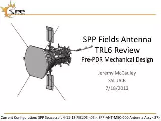
SPP Fields Antenna TRL6 Review Pre-PDR Mechanical Design. Jeremy McCauley SSL UCB 7/18/2013. Current Configuration: SPP Spacecraft 4-11-13 FIELDS <05>, SPP-ANT-MEC-000 Antenna Assy <27>. TRL6 Development. Stowed along SC for Launch Support at ends and midspan Angled to fit on panels

E N D
SPP Fields AntennaTRL6 ReviewPre-PDR Mechanical Design Jeremy McCauley SSL UCB 7/18/2013 Current Configuration: SPP Spacecraft 4-11-13 FIELDS <05>, SPP-ANT-MEC-000 Antenna Assy <27>
TRL6 Development • Stowed along SC for Launch • Support at ends and midspan • Angled to fit on panels • TRL6 Development Tasks • Verify dynamic response
Whip Vibe • Restrained as designed: • One end fixed, mid point clamped, end fork • Bent to match Stowed configuration • First Resonant Frequency: 6 to 10 Hz • No permanent deformations or distortions
Backup Slides Current Configuration: SPP Spacecraft 4-11-13 FIELDS <05>, SPP-ANT-MEC-000 Antenna Assy <27>
Agenda • TRL6 Development Tasks • Mechanical Design • Thermal Design • BB Tests
Design Concept • Equal exposed length • Coplanar with TPS • Greatest length, greatest separation • Stowed along SC for Launch • Preamp located as close to ANT as possible
Design Development • Hinge • Similar to THEMIS FGB designed at SSL • Behind TPS at ordinary flight environments • Mounting accomodation worked with APL
Design Development • Outboard Segment • Exposed to intense sunlight • Shield and Isolate to provide quick thermal cooling
Thermal Design Concept Thermal Choke • Hinge and Preamp Behind TPS • Whip >1300 C • Thermal Choke • Shield for Stub • Shield from TPS • Radiator for Preamp TPS
Thermal Design Concept • Sapphire Isolators on Whip, Stub and Shield • (APL Data) • Alumina inside Stub • FR4 or similar all other places • Titanium Mounting Foot Model
BB Testing • Thermal Isolators and Shield • PROMES • SAO • GSFC • Whip Vibe • FWB • Hinge and Stub Cage
Thermal Choke TTM Whip Disk Whip Choke Choke Water Cooling
TTM Choke Thermal Results • Thermal Balance
Thermal Shield TTM Shield Clamp Bracket Water Cooled Stub
TTM Shield Thermal Results • Thermal Balance
TTM Shield Lessons Learned • Re-crystalization of Titanium • Has no observed effect on bracket • Melting of silver coating on bolts • Might create gaps on joints • Rapid heating • Probably deformed shield
Thermal Distortion Testing • 28 inch sample • ~10 inch heated section • Monitor motion of tip • Max deflection ~0.06” • Larger than desired
Thermal Design Conclusions • Niobium good for temperatures • Distortion to be characterized before PDR • Thermal Choke works • Shield for Stub gives sufficient isolation • A286 Screws • No Silver • To be verified with static furnace test over the next month
Whip Vibe Anomaly • End Bent at Fork • No contact from personnel observed • Transverse to fork when found • Most likely due to fixture during resonant case • First Y-axis random • Ejected test article • Test rerun for verification
FWB and Hinge Testing • Testing FWB for torque over temperature range • Second Generation • Ambient Torque Testing verified function as desired • Testing Hinge Form and Function • Already TRL6 due to previous Flight Designs
TRL6 Conclusions • Materials • a/e data complete • Insulators chosen • Thermal response • Choke, shield work • Screw material in final test • Tube distortion in testing • SAO Beam testing next month • 2 (later 6) beams • Dynamic response TRL6 by PDR