CHAPTER 23 Mass Air Flow Sensors
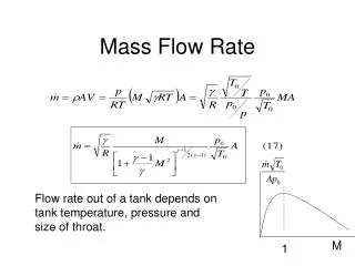
1k likes | 3.63k Vues
CHAPTER 23 Mass Air Flow Sensors. OBJECTIVES. After studying Chapter 23, the reader will be able to: Prepare for ASE Engine Performance (A8) certification test content area “E” (Computerized Engine Controls Diagnosis and Repair). Discuss how MAF sensors work.

CHAPTER 23 Mass Air Flow Sensors
E N D
Presentation Transcript
CHAPTER 23 Mass Air Flow Sensors
OBJECTIVES After studying Chapter 23, the reader will be able to: • Prepare for ASE Engine Performance (A8) certification test content area “E” (Computerized Engine Controls Diagnosis and Repair). • Discuss how MAF sensors work. • List the methods that can be used to test MAF sensors. • Describe the symptoms of a failed MAF sensor. • List how the operation of the MAF sensor affects vehicle operation. • Discuss MAF sensor rationality tests.
False air Mass airflow (MAF) sensor Speed density Tap test Vane airflow (VAF) sensor KEY TERMS
FIGURE 23–1 A vane air flow (VAF) sensor. AIRFLOW SENSORS • Older electronic fuel-injection systems that use airflow volume for fuel calculation usually have a movable vane in the intake stream. • The vane is part of the vane airflow (VAF) sensor. • The vane is deflected by intake airflow.
AIRFLOW SENSORS • The vane airflow sensor used in Bosch L-Jetronic, Ford, and most Japanese electronic port fuel-injection systems is a movable vane connected to a laser-calibrated potentiometer. • The vane is mounted on a pivot pin and is deflected by intake airflow proportionate to air velocity. • As the vane moves, it also moves the potentiometer. • This causes a change in the signal voltage supplied to the computer
FIGURE 23–2 A typical air vane sensor with the cover removed. The movable arm contacts a carbon resistance path as the vane opens. Many air vane sensors also have contacts that close to supply voltage to the electric fuel pump as the air vane starts to open when the engine is being cranked and air is being drawn into the engine. AIRFLOW SENSORS
What Is the Difference Between an Analog and a Digital MAF Sensor? • Some MAF sensors produce a digital DC voltage signal whose frequency changes with the amount of airflow through the sensor. The frequency range also varies with the make of sensor and can range from 0- to 300-Hz for older General Motors MAF sensors to 1,000- to 9,000-Hz for most newer designs. • Some MAF sensors, such as those used by Ford and others, produce a changing DC voltage, rather than frequency, and range from 0- to 5-volts DC.
FIGURE 23–3 This five-wire mass air flow sensor consists of a metal foil sensing unit, an intake air temperature (IAT) sensor, and the electronic module. MASS AIRFLOW SENSOR TYPESHOT FILM SENSOR • The hot film sensor uses a temperature-sensing resistor (thermistor) to measure the temperature of the incoming air. • Through the electronics within the sensor, a conductive film is kept at a temperature 70°C above the temperature of the incoming air.
FIGURE 23–4 The sensing wire in a typical hot wire mass air flow sensor. MASS AIRFLOW SENSOR TYPESHOT WIRE SENSOR • The hot wire sensor is similar to the hot film type, but uses a hot wire to sense the mass airflow instead of the hot film. • Like the hot film sensor, the hot wire sensor uses a temperature-sensing resistor (thermistor) to measure the temperature of the air entering the sensor.
KARMAN VORTEX SENSORS • There are two basic designs of Karman Vortex air flow sensors. • The two types include: • Ultrasonic • Pressure-type
FIGURE 23–5 A Karman Vortex air flow sensor uses a triangle-shaped rod to create vortexes as the air flows through the sensor. The electronics in the sensor itself converts these vortexes to a digital square wave signal. KARMAN VORTEX SENSORS
PCM USES FOR AIRFLOW SENSORS • The PCM uses the information from the airflow sensor for the following purposes: • Airflow sensors are used mostly to determine the amount of fuel needed and base pulse-width numbers. The greater the mass of the incoming air, the longer the injectors are pulsed on. • Airflow sensors back up the TP sensor in the event of a loss of signal or an inaccurate throttle position sensor signal. If the MAF sensor fails, then the PCM will calculate the fuel delivery needs of the engine based on throttle position and engine speed (RPM).
The Dirty MAF Sensor Story • The owner of a Buick Park Avenue equipped with a 3800 V-6 engine complained that the engine would hesitate during acceleration, showed lack of power, and seemed to surge or miss at times. A visual inspection found everything to be like new, including a new air filter. There were no stored diagnostic trouble codes (DTCs). A look at the scan data showed airflow to be within the recommended 3 to 7 grams per second. A check of the frequency output showed the problem.
The Dirty MAF Sensor Story • Idle frequency 2.177 kHz (2,177 Hz) • Normal frequency at idle speed should be 2.37 to 2.52 kHz. Cleaning the hot wire of the MAF sensor restored proper operation. The sensor wire was covered with what looked like fine fibers, possibly from the replacement air filter.
What Is Meant By a “High-Authority Sensor”? • A high-authority sensor is a sensor that has a major influence over the amount of fuel being delivered to the engine. For example, at engine start-up, the engine coolant temperature (ECT) sensor is a highauthority sensor and the oxygen sensor (O2S) is a low-authority sensor. However, as the engine reaches operating temperature, the oxygen sensor becomes a high-authority sensor and can greatly affect the amount of fuel being supplied to the engine.
TESTING MASS AIRFLOW SENSORS • VISUAL INSPECTION • MAF SENSOR OUTPUT TEST • TAP TEST • DIGITAL METER TEST OF A MAF SENSOR
What Is False Air? • Airflow sensors and mass airflow (MAF) sensors are designed to measure all the air entering the engine. If an air inlet hose was loose or had a hole, extra air could enter the engine without being measured. This extra air is often called false air. Because this extra air is unmeasured, the computer does not provide enough fuel delivery and the engine operates too lean, especially at idle. A small hole in the air inlet hose would represent a fairly large percentage of false air at idle, but would represent a very small percentage of extra air at highway speeds. • To diagnose for false air, look at long-term fuel trim numbers at idle and at 3000 RPM.
FIGURE 23–6 Carefully check the hose between the MAF sensor and the throttle plate for cracks or splits that could create extra (false) air into the engine that is not measured by the MAF sensor. What Is False Air?
MAF SENSOR CONTAMINATION • Dirt, oil, silicon, or even spiderwebs can coat the sensing wire. • Because it tends to insulate the sensing wire at low airflow rates, a contaminated sensor often overestimates the amount of air entering the engine at idle, and therefore causes the fuel system to go rich. • At higher engine speeds near wide-open throttle (WOT), the contamination can cause the sensor to underestimate the amount of air entering the engine. • As a result, the fuel system will go lean, causing spark knock and lack of power concerns. • To check for contamination, check the fuel trim numbers.
MAF-RELATED DIAGNOSTIC TROUBLE CODES • The diagnostic trouble codes (DTCs) associated with the mass airflow and air vane sensors include:
The Unplug It Test • If a sensor is defective yet still produces a signal to the computer, the computer will often accept the reading and make the required changes in fuel delivery and spark advance. If, however, the sensor is not reading correctly, the computer will process this wrong information and perform an action assuming that information being supplied is accurate. For example, if a mass airflow (MAF) sensor is telling the computer that 12 grams of air per second is going into the engine, the computer will then pulse the injector for 6.4 ms or whatever figure it is programmed to provide.
The Unplug It Test • However, if the air going into the engine is actually 14 grams per second, the amount of fuel supplied by the injectors will not be enough to provide proper engine operation. If the MAF sensor is unplugged, the computer knows that the sensor is not capable of supplying airflow information, so it defaults to a fixed amount of fuel based on the values of other sensors such as the TP and MAP sensors. “If in doubt, take it out.”
The Unplug It Test • If the engine operates better with a sensor unplugged, then suspect that the sensor is defective. A sensor that is not supplying the correct information is said to be skewed. The computer will not see a diagnostic trouble code for this condition because the computer can often not detect that the sensor is supplying wrong information.
The Rich Running Toyota • A Toyota failed an enhanced emission test for excessive carbon monoxide, which is caused by a rich (too much fuel) air–fuel ratio problem. After checking all of the basics and not finding any fault in the fuel system, the technician checked the archives of the International Automotive Technicians Network (www.iatn.net) and discovered that a broken spring inside the air flow sensor was a possible cause. The sensor was checked and a broken vane return spring was discovered. Replacing the air flow sensor restored the engine to proper operating conditions and it passed the emission test.
SUMMARY • A mass airflow sensor actually measures the density and amount of air flowing into the engine, which results in accurate engine control. • An air vane sensor measures the volume of the air, and the intake air temperature sensor is used by the PCM to calculate the mass of the air entering the engine. • A hot wire MAF sensor uses the electronics in the sensor itself to heat a wire 70°C above the temperature of the air entering the engine.
REVIEW QUESTIONS • How does a hot film MAF sensor work? • What type of voltage signal is produced by a MAF? • What change in the signal will occur if engine speed is increased? • How is a MAF sensor tested? • What is the purpose of a MAF sensor? • What are the types of airflow sensors?
CHAPTER QUIZ 1. A fuel-injection system that does not use a sensor to measure the amount (or mass) of air entering the engine is usually called a(n) ________ type of system. • Air vane-controlled • Speed density • Mass airflow • Hot wire
CHAPTER QUIZ 2. Which type of sensor uses a burn-off circuit? • Hot wire MAF sensor • Hot film MAF sensor • Vane-type airflow sensor • Both a and b
CHAPTER QUIZ 3. Which sensor has a switch that controls the electric fuel pump? • VAF • Hot wire MAF • Hot filter MAF • Karman Vortex sensor
CHAPTER QUIZ 4. Two technicians are discussing Karman Vortex sensors. Technician A says that they contain a burn-off circuit to keep them clean. Technician B says that they contain a movable vane. Which technician is correct? • Technician A only • Technician B only • Both Technicians A and B • Neither Technician A nor B
CHAPTER QUIZ 5. The typical MAF reading on a scan tool with the engine at idle speed and normal operating temperature is ________. • 1 to 3 grams per second • 3 to 7 grams per second • 8 to 12 grams per second • 14 to 24 grams per second
CHAPTER QUIZ 6. Two technicians are diagnosing a poorly running engine. There are no diagnostic trouble codes. When the MAF sensor is unplugged, the engine runs better. Technician A says that this means that the MAF is supplying incorrect airflow information to the PCM. Technician B says that this indicates that the PCM is defective. Which technician is correct? • Technician A only • Technician B only • Both Technicians A and B • Neither Technician A nor B
CHAPTER QUIZ 7. A MAF sensor on a General Motors 3800 V-6 is being tested for contamination. Technician A says that the sensor should show over 100 grams per second on a scan tool display when the accelerator is depressed to WOT on a running engine. Technician B says that the output frequency should exceed 7,000 Hz when the accelerator pedal is depressed to WOT on a running engine. Which technician is correct? • Technician A only • Technician B only • Both Technicians A and B • Neither Technician A nor B
CHAPTER QUIZ 8. Which airflow sensor has a dampening chamber? • A vane airflow • A hot film MAF • A hot wire MAF • A Karman Vortex
CHAPTER QUIZ 9. Air that enters the engine without passing through the airflow sensor is called ________. • Bypass air • Dirty air • False air • Measured air
CHAPTER QUIZ 10. A P0102 DTC is being discussed. Technician A says that a sensor circuit shorted-to-ground can be the cause. Technician B says that an open sensor voltage supply circuit could be the cause. Which technician is correct? • Technician A only • Technician B only • Both Technicians A and B • Neither Technician A nor B