Flow Sensors
910 likes | 2.2k Vues
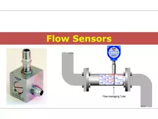
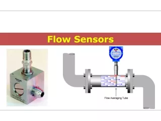
Flow Sensors. Reasons for Flow Metering. Plant control, for product quality and safety reasons. Custody transfer, both interplant and selling to outside customers. Filling of containers, stock tanks and transporters.

Flow Sensors
E N D
Presentation Transcript
Reasons for Flow Metering • Plant control, for product quality and safety reasons. • Custody transfer, both interplant and selling to outside customers. • Filling of containers, stock tanks and transporters. • Energy, mass balancing for costing purpose and health monitoring of heat exchangers. • Health monitoring of pipelines and on-line analysis equipment, Government and company legislation may dictate the use here of such equipment.
Types of Flow Meters • Inferential type flow meters • Quantity flow meters • Positive displacement meters • Metering pumps • Mass flow meters
Inferential Meters • The inferential type meters are so-called because rather than measuring the actual volume of fluid passing through them, they “infer” the volume by measuring some other aspect of the fluid flow and calculating the volume based on the measurements
Inferential Meters • Variable head or differential meters • Variable area meters • Magnetic meters • Turbine Meters • Target meters • Thermal flow meters • Vortex meters • Ultrasonic flow meters
Differential Pressure Meters • Orifice Plate • Dall Tube • Venturi Tube • Pitot Tube • Rota meter • Target mater • Averaging Pitot • Nozzle • Spring Loaded • Intake Meter • Elbow Meter • Bypass Meter
Parts of differential flow meters • Primary element (Part of meter used to restrict the fluid flow in pipe line to produce differential pressure) They include • Orifice plate • Venturi tubes • Flow nozzles • Pitot tube etc.
Parts of differential flow meters • Secondary element (measure the differential pressure produced by primary elements and convert them to usable forces or signals ) Secondary elements; • Manometers • Bellow meters • Force balance meters etc.
Obstruction Meters • Orifice Meters • Venturi Meters • Flow Nozzles
Flow Through an Orifice Meter P1 P2 d D P1 P
Flow Through an Orifice Meter • Cheapest and Simplest • But biggest pressure drop and power lost (C~0.6 - 0.7) • Side Note: • Pressure drop caused by friction and turbulence of shear layer downstream of vena contracta 10k Re 0.85 5000 100k 0.6 b=d/D 0.1 0.8
Flow Through an Venturi Meter In a venturi, 0.95 < C < 0.98 Advantage: Pressure recovery Uses little power
Flow Through a Nozzle P1 P2 P1 P P2
Flow Through a Nozzle Shorter and cheaper than venturi But larger pressure drop. Thus, more power lost in operating. 0.98 C 0.86 105 103 Re
Flow Through a Nozzle Basic Equations: a.) Continuity: mass in = mass out b.) Bernoulli’s Eqn. Total pressure is constant throughout
Flow Through a Nozzle Y = Compressibility Factor =1 for incompressible flow or when DP<< Pabs C= Discharge Coefficient =f(Re) and nature of specific flow meter DP P
Rotameter, variable-area-flowmeter • Force balance • Drag Force • Gravity • Buoyancy • (usually negligible) Derived on next slide
Turbine Flow Meters • It consists of a multi-bladed rotor mounted at right angles to the flow and suspended in the fluid stream on a free-running bearing. • Used for measurements of liquid, gas and very low flow rates. • It basically works on the principle of turbine. • The diameter of the rotor is very slightly less than the inside diameter of the metering chamber, and its speed of rotation is proportional to the volumetric flow rate. • The rotational speed is a direct function of flow rate and can be sensed by magnetic pick-up coil. • As each rotor blade passes the magnetic pick-up coil, it generates a voltage pulse which is a measure of flow rate.
Turbine Flow Meters • Electrical pulses can be counted and totalized and it gives the total flow rate.
Target Flow Meters -- It measures flow by measuring the amount of force exerted by the flowing fluid on a target suspended in the flow stream. -- The fluid flow develops a force on target which is proportional to the square of the flow.--measure the flow of liquids and gases, such as water, air, industrial gases, and chemicals. Q=K(F)1/2WhereQ= flow rateK = a known coefficientF = force
Magnetic Flow Meters The physical principle at work is Faraday's law of electromagnetic induction, it states that whenever a conductor moves through a magnetic field of given strength , a voltage is induced in a conductor which is proportional to the relative velocity between the conductor and the magnetic field.
Magnetic Flow Meters (Cont‘d) For high corrosive applications Induced voltage is given by • E=CBLv • v=E/CBL Equation of continuity: • Q=vA so • Q=EA/CBL • Q = KE WHERE • K= A/CBL=CONSTANT • So induced voltage is directly and linear proportional to the volumetric flow rate.
Thermal Flow Meters Based on specific heat equation which is given as Q=WCP(T2 – T1) W= Q/CP(T2 – T1) Where Q= heat transfer W=mass flow rate of fluid Cp=specific heat of fluid T1=initial temperature of the fluid after heat has been transferred T2= final temperature after heating the fluid
Vortex Flow Meters Swirl Meter • Operates on principle of vortex precession. • It gives an output in the form of pulses whose frequency is proportional to the fluid flow rate. • In the area where expansion occurs , the swirling flow precceds or oscillates at a frequency proportional to the fluid flow rate. • Each high velocity vortex passed the thermistor, changes the resistance and since a constant current is applied, the resistance changes is converted into voltage pulses which are amplified , filtered and transformed into constant amplitude high level pulses of square waveform.
Vortex Flow Meters (Cont‘d) • Based on the phenomenon of Vortex shedding. • The frequency at which the vortices are formed is directly proportional to the fluid velocity. • The velocity and pressure distribution in the fluid around the sluff body change at the same frequency as the vortex shedding frequency. Vortex Shedding Meter
Ultrasonic Flow Meters Time difference Type Doppler Type V= ΔfC/2fo cosθ Where C=velocity of sound in fluid Θ=angle of transmitter and receiver wrt to pipe axis fo = frequency of transmission Δf = difference between transmitted and received frequency • TAB-TBA=2LVcosθ/C • Where • L=acoustic path length between A and B • C=velocity of sound in fluid • Θ=angle of path wrt to pipe axis • V=velocity of fluid in pipe
Inferential Meters Advantages • Very good repeatability • Reduced susceptibility to fouling and deposits • Less sensitive to viscosity changes • Available in large sizes, good value for high flow rates • Low maintenance • Registers near zero flow rate Disadvantages • High pressure drop that increases drastically with viscosity • Relatively high cost • Indirect measurement
Coriolis Mass Flowmeter In the Coriolis meter the fluid is passed through a tube. The tubes are available in different design like tubes of U-shape or horseshoe-shaped. The tubes can either be curved or straight. When two tubes are used the flow is divided when entering the meter and then recombined. The flow when enters the tube encounters oscillating excitation force that causes the tubes to vibrate at a fixed frequency. The vibration is induced in the direction that is perpendicular to flow of fluid. This creates the rotation frame of reference. Consider the tube during oscillation moving up and downward, when the tube is moving upward the fluid flowing in it tends to resist this and forces it downward. When the tube moves in the opposite direction, so does the fluid and a twist in introduced in the tube. All this might not be visible by directly observing. The twist at inlet of fluid and outlet of fluid results in phase difference or time lag and that is dependent on the fluid mass passing through the tube.
Quantity Flow Meters • Used for the measurement of small percentage of industrial flow rates. • These meters operate by passing the fluid to be measured through the meter in separate and distinct increments of alternately feeling and emptying containers of known fixed capacity. • The number of times the container is filled and emptied gives the quantity of flow. • Types are: • Positive displacement meters • Metering pumps
PD Rotary Meters ( Displacement Meters) Positive displacement flow meters, also know as PD meters, measure volumes of fluid flowing through by counting repeatedly the filling and discharging of known fixed volumes.
PD Rotary Meters ( Displacement Meters) Principle of Operation • POSITION 1. As the bottom impeller rotates in a counterclockwise direction towards a horizontal position, fluid enters the space between the impeller and cylinder. • POSITION 2. At the horizontal position, a definite volume of fluid is contained in the bottom compartment.
PD Rotary Meters ( Displacement Meters) Principle of Operation • POSITION 3. As the impeller continues to turn, the volume of fluid is discharged out the other side. • POSITION 4. The top impeller, rotating in opposite direction, has closed to its horizontal position confining another known and equal volume of fluid.
PD Rotary Meters ( Displacement Meters) • Oval Gear • Nutating Disk • Oscillating Piston • Multi Piston • Rotating Impellers • Rotating Valve • Birotor • Roots Meter • Helix Meters
PD Rotary Meters ( Displacement Meters) Nutating Disk • A nutating disc meter has a round disc mounted on a spindle in a cylindrical chamber. • By tracking the movements of the spindle, the flowmeter determines the number of times the chamber traps and empties fluid.
PD Rotary Meters ( Displacement Meters) Oval Gear • Two identical oval rotors mesh together by means of slots around the gear perimeter. • The oval shaped gears are used to sweep out an exact volume of the liquid passing through the measurement chamber during each rotation.
PD Rotary Meters ( Displacement Meters) Oval Gear • The flow rate can be calculated by measuring the rotation speed.
PD Rotary Meters ( Displacement Meters) Roots Meter • The roots meter is similar in many respects to the oval gear meter. • Two-lobed impellers rotate in opposite directions to each other within the body housing.
PD Rotary Meters ( Displacement Meters) Roots Meter • These peanut-shaped gears sweep out an exact volume of liquid passing through the measurement chamber during each rotation. • The flow rate can be calculated by measuring the rotation speed.
PD Rotary Meters ( Displacement Meters) Rotating Impeller
PD Rotary Meters ( Displacement Meters) High accuracy over a wide range of viscosities and flow rates up to 2000 cP with proper clearances. Extremely good repeatability on high viscosity fluids, very low slippage, long life if little or no abrasive material in the fluid Low pressure drop Advantages
PD Rotary Meters ( Displacement Meters) Advantages • Special construction available for high viscosities and temperatures • Can register near zero flow rate • Measures directly, not an inferential device, for more consistent results • Easy to repair and economical.