Sensors
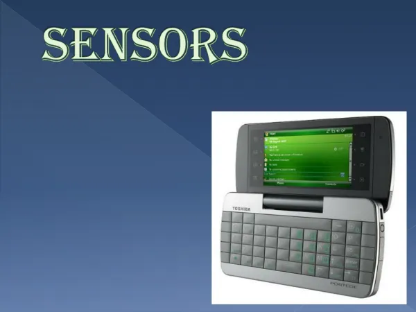
Material taken from Robotics with the Boe-Bot. Sensors. Where Are We Going?. Sumo-Bot competitions. Devices that Contain Sensors. The boebot uses sensors to interact with its environment.

Sensors
E N D
Presentation Transcript
Where Are We Going? Sumo-Bot competitions
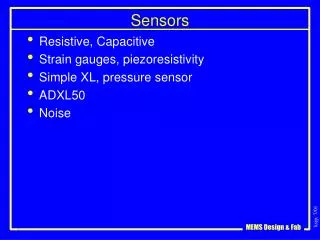
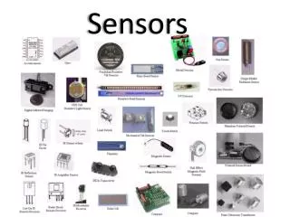
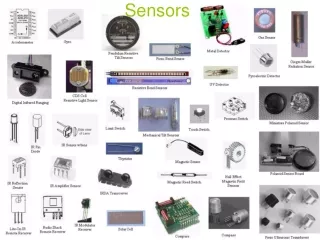
Devices that Contain Sensors The boebot uses sensors to interact with its environment. There are a variety of sensors used for a variety of purposes: smoke, sound,rotation/tilt,vibration, magnetic orientation, temperature, humidity, pressure, proximity, distance, light, and so on.
Ultrasonic Distance Sensor PING Ultrasonic Range Finder Parallax Tutorial • PING ultrasonic distance sensor provides precise distance measurements from about 2 cm (0.8 inches) to 3 meters (3.3 yards). • It works by transmitting an ultrasonic burst and providing an output pulse that corresponds to the time required for the burst echo to return to the sensor. • By measuring the echo pulse width the distance to target can easily be calculated.
Theory of Operation The PING sensor emits a short ultrasonic burst and then "listens" for the echo. Under control of a host microcontroller (trigger pulse), the sensor emits a short 40 kHz (ultrasonic) burst. This burst travels through the air at about 1130 feet per second, hits an object and then bounces back to the sensor. The PING sensor provides an output pulse to the host that will terminate when the echo is detected, hence the width of this pulse corresponds to the distance to the target.
Simple to Connect http://learn.parallax.com/
Programs Code---Without Library Support With the Ping library: #include <Ping.h> int PingPin = 9; Ping sonar(PingPin); void setup() { Serial.begin(9600); } void loop() { delay(50); sonar.fire(); Serial.print("Ping: "); Serial.print(sonar.inches()); Serial.println("in"); }
The IR Detector The IR detector is only looking for infrared that’s flashing on and off 38,500 times per second. It has built-in optical filters that allow very little light except the 980 nm infrared. It also has an electronic filter that only allows signals around 38.5 kHz to pass through. This prevents IR interference from common sources such as sunlight and indoor lighting.
Schematics Ground Ground Ground Ground http://learn.parallax.com/
IR Detection Range Less series resistance will make an LED glow more brightly. Brighter IR LEDs can make it possible to detect objects that are further away.
Detecting IR The key to making each IR LED/detector pair work is to send 1 ms of a 38.5 kHz IR signal, and then, immediately store the IR detector’s output in a variable. The IR detector’s output state is HIGH (1) when it receives NO IR signal. When the IR detector sees the 38500 Hz signal reflected by an object, its output is LOW (0). The IR detector’s output only stays LOW for a fraction of a millisecond after the 38.5 kHz signal is sent, so it’s essential to store the IR detector’s output in a variable immediately after sending the 38.5 kHz signal.
Code for Testing IR int LeftIRDec = 11; int LeftIREmit = 10; int RightIRDec = 4; int RightIREmit = 5; void setup() { pinMode(LeftIRDec, INPUT); pinMode(LeftIREmit, OUTPUT); pinMode(RightIRDec, INPUT); pinMode(RightIREmit, OUTPUT); Serial.begin(9600); } void loop() { int irLeft = irDetect(LeftIREmit, LeftIRDec, 38000); int irRight = irDetect(RightIREmit, RightIRDec, 38000); Serial.print(irLeft); Serial.print(" "); Serial.println(irRight); delay(100); } int irDetect(int irLedPin, int irReceiverPin, long frequency) { tone(irLedPin, frequency, 8); delay(1); int ir = digitalRead(irReceiverPin); // IR receiver -> ir variable delay(1); // Down time before recheck return ir; // Return 1 no detect, 0 detect }
Object Detection And Avoidance Code Customizing the code: • Assign names to the pins • Remove the call to tone() in setup() • Change from avoidance to pursuit • More?
The QTI is a reflective object sensor. There’s an infrared LED behind its clear window and an infrared phototransistor behind its black window. When the infrared light emitted by the LED reflects off a surface and returns to the black window, it strikes the infrared phototransistor’s base, causing it to conduct current. The more infrared incident on the phototransistor’s base, the more current it conducts. How it Works
Like an RC Circuit http://learn.parallax.com/
Code for Testing QTIs int LeftQTI = 8; int RightQTI = 2; void setup() { Serial.begin(9600); } void loop() { long tLeft = rcTime(LeftQTI); long tRight = rcTime(RightQTI); Serial.print("tLeft = "); Serial.print(tLeft); Serial.println(" us"); Serial.print("tRight = "); Serial.print(tRight); Serial.println(" us"); delay(1000); } long rcTime(int pin) { // ..returns decay time pinMode(pin, OUTPUT); // Charge capacitor digitalWrite(pin, HIGH); // ..by setting pin ouput-high delay(1); // ..for 5 ms pinMode(pin, INPUT); // Set pin to input digitalWrite(pin, LOW); // ..with no pullup long time = micros(); // Mark the time while(digitalRead(pin)); // Wait for voltage < threshold time = micros() - time; // Calculate decay time return time; // Return decay time }
Code for Detecting Reflection Customizing the code: • Assign names to the pins • Remove the call to tone() in setup() • Use multiple QTI sensors • More?
Simple Connections http://learn.parallax.com/