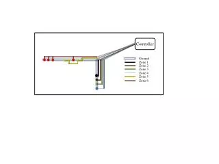
Flight Controller Diagram
This document outlines the flight control system for Unity IV, developed by BYU, USU, and the University of Utah. It features a battery pack (24V, 1.5A) powering multiple components, including solenoid valves, a ball valve, and an igniter. Equipped with a safety switch for the motor ignition, it ensures the last person on the launch pad has control, minimizing risks. The system employs a Tiny Tiger multitasking controller for efficient deployment of the separation ring and main chute at specific altitudes. Integrated data logging is provided by DataBrick, enhancing flight monitoring and safety.
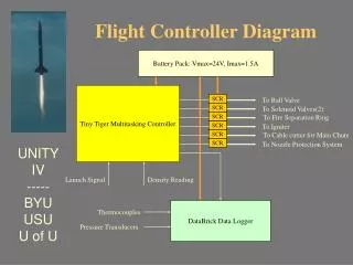

Flight Controller Diagram
E N D
Presentation Transcript
Battery Pack: Vmax=24V, Imax=1.5A Flight Controller Diagram Tiny Tiger Multitasking Controller SCR To Ball Valve SCR To Solenoid Valves(2) To Fire Separation Ring SCR SCR To Igniter To Cable cutter for Main Chute SCR SCR To Nozzle Protection System UNITY IV ----- BYU USU U of U Launch Signal Density Reading DataBrick Data Logger Thermocouples Pressure Transducers
Launch Signal Transmitter (Ground) Receiver (On Board) To Tiny Tiger to initiate launch UNITY IV ----- BYU USU U of U The Transmitter box will be equipped with a key switch for safety. The last person on the launch pad will have the key with him so the motor will not be able to be ignited prematurely. This will eliminate danger and ensure safety for everyone.
Power Specifications • Separation Ring: 7W, 1.5A, 3sec. • Igniter: 6V (Equivalent of 4AA) • Ball Valve: 24V, 2.5sec. • Solenoid Valves: 24V, Fast • DataBrick: 4.8W, 12V • Microcontroller: 5V UNITY IV ----- BYU USU U of U
Specifications • Fire Separation Ring / Deploy Drogue at apogee • Deploy Main Chute at a certain altitude below apogee • Deploy Main Chute of Nose Cone after a certain number of seconds has elapsed • Close Valves and Nozzle Protection System UNITY IV ----- BYU USU U of U
More Specifications • Two flight controllers: Main Controller in the booster and Nose Cone Controller in the Nose Cone • Nose Cone Controller will have separate battery supply • Battery will power: Valves(Ball and Solenoid) Main Controller Firing of the Separation Ring Igniter Nozzle Protection System Data Logger (DataBrick) UNITY IV ----- BYU USU U of U