Download
1 / 17
320 likes | 1.45k Vues
Medical Image Reconstruction Topic 5: Synthetic Aperture Ultrasound Imaging. Professor Yasser Mostafa Kadah – www.k-space.org. Recommended R eferences.

E N D
Medical Image ReconstructionTopic 5: Synthetic Aperture Ultrasound Imaging Professor Yasser Mostafa Kadah – www.k-space.org
Recommended References • Diagnostic Ultrasound: Physics and Equipment, 2nd ed., by Peter R. Hoskins (Editor), Kevin Martin (Editor), Abigail Thrush (Editor) Cambridge University Press, 2010. • Papers cited in this lecture
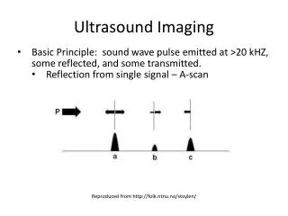
Scanning in Linear Arrays • Element selection of active group to use in transmission and reception to acquire a line • Move active group by one element to acquire another line and so on • Same for linear and curvilinear array transducers
Beamforming • The part of scanner that determines the shape, size and position of the ultrasound beams by controlling electrical signals to and from the transducer array elements
Beamforming • Transmission focusing • Reception focusing • Delay-Sum beamforming
Delay Calculation from Geometry • Simple path length difference given array geometry and focus point coordinates • Relative to longest path • Assume c=1540m/s • Focusing: =0 • Same for transmission and reception focusing calculations
Dynamic Reception Focusing • Change electronic focusing delays with time to follow received signal depth • Dynamic delays • At time T focus is at depth (cT/2)
Multiple Transmission Zones • It is not possible to focus at two locations in transmission • Acquire same field twice with two different transmission foci and combine images to get the best beam shape
Apodization • Windowing of aperture • Recall that the field is the Fourier transform of the aperture • Lower side lobes (+) • Wider main lobe (-)
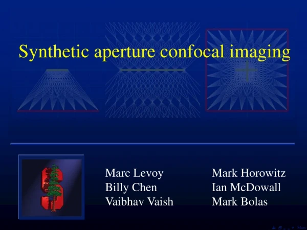
Synthetic Aperture Imaging • Uses a very small aperture (1 element) in transmission and collect data from all elements • Allows off-line processing of collected data to generate images with different transmission and reception apertures and beamforming (by superposition) Combine
Synthetic Aperture Data • Given as a 3-D array of size NxNxM • N: number of elements in array probe • M: number of points in the received signal • The array data(n, m,:) represents ultrasound data samples received from element m as a result of a transmission by element n • Can use linearity to form an arbitrary imaging system by selecting number of elements in transmission and reception as well as their phasing for focusing/steering
Synthetic Aperture Imaging: Example • Problem definition: Given synthetic aperture data array Data(128,128,512), reconstruct an image with the following specifications: • 8 element aperture in transmission and reception • No transmission focusing • Single reception focus at 5 cm • No apodization • Sampling rate of ultrasound line is 10 MSa/s • Element size= 1 mm, assume nearly zero element spacing
Synthetic Aperture Imaging: Example • Step #1: Element selection for line 1 • 8-element aperture: elements 1:8 are selected • Matlab: Data1= Data(1:8,1:8, : ) • Resultant data array size: 8x8x512 (3D array) • Step #2: Obtain transmission using 8 elements – no focus • Superposition: Sum all data from transmission elements 1:8 • Matlab: DataTr1= sum(Data1(1:8, : , : ), 1) (sums over 1st dim) • Resultant data array size: 8x512 (2D array)
Synthetic Aperture Imaging: Example • Step #3: Compute focusing delays for reception • Calculate focusing delays corresponding to 5 cm focal depth given the array geometry and store in array delay1(8x1 array) • Convert delays to samples given thatdata point corresponds to 1/10e6= 0.1 s: delaysamples1= delay1 / (0.1e-6) • For each point, sum signals from all 8 reception elements with their respective delays to obtain image line • ImageLine(n)= DataTr1(1, n+delaysamples1(1)+ DataTr1(2, n+delaysamples1(2))+ … DataTr1(8, n+delaysamples1(8)) • Step #4: Repeat for all image lines • Line 2uses element 2:9, line 3 uses 3:10, etc.
Exercise • Use one of data sets available on the class web site to reconstruct an ultrasound image. Assume any missing imaging parameters outside those given in the data set description. • Do a literature/patent search on the topic of ultrasound beamforming and scan conversion and come up with a list of all relevant references that should be the starting point for doing research on the subject.