Biasing Circuit
Biasing Circuit. Establish a constant voltage V B. Current-derived negative feedback.The degree of success of the negative feedback is Bias Stability. cut-off conditions ,. Example.

Biasing Circuit
E N D
Presentation Transcript
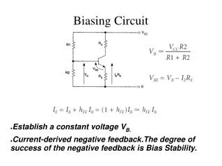
Biasing Circuit • Establish a constant voltage VB. • Current-derived negative feedback.The degree of success of the negative feedback is Bias Stability.
Example • A transistor is to be biased at a collector current of 1 mA when a 12-V power supply is applied. Using the above figure, determine the values of R1, R2, and RE if 3.4 V is to be dropped across RE and if the current through R2 is to be 10 IBQ. Assume that for the transistor used, VBEQ = 0.6 V and hFE = 100.
Example Also, VB = VRE + VBE = 3.4 + 0.6 = 4 V. VR1 = VCC – VB = 12 – 4 = 8 V
Common Emitter Amplifier Transconductance=how much ICchanges with a fluctuation in VBE. In practice, VT = 26 mV at room temperature The terminal voltage gain is therefore
Model • Basic Equation • Equivalent Circuit • Simulation model