Understanding Graphics System Transformation and Clipping Algorithms
Learn about OpenGL light model issues, geometric processing tasks, implementation strategies, and various clipping algorithms used in graphics systems.

Understanding Graphics System Transformation and Clipping Algorithms
E N D
Presentation Transcript
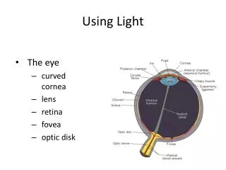
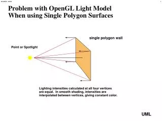
Problem with OpenGL Light ModelWhen using Single Polygon Surfaces single polygon wall Point or Spotlight Lighting intensities calculated at all four vertices are equal. In smooth shading, intensities are interpolated between vertices, giving constant color.
Geometric Processing Rasterization Display Modeling Implementation Tasks:What goes on inside the graphics system • Transformation &Normalization • Clipping • Hidden surface removal • Representa-tion of geometric objects • Scan conversion • Antialiasing • Color mapping
Implementation Strategies Object oriented: for(each_object) render (object); - Pipelined vertex oriented renderer fits this strategy - Any primitive potentially affects any set of pixels in the frame buffer/z buffer - Usually implemented in hardware Image oriented: for (each_pixel) assign_a_color (pixel); - Requires limited display memory - Can exploit coherence in incremental algorithms - Requires complex geometric data structure
Y Y Y Y X X X X Z Z Z Z Transformation Sequence Normalized Device Coords. Screen Coords. Clip Coords. Object Coords. Eye Coords. Implementation: 4 x 4 matrix multiplication in homogeneous coords.
y x Graphics Pipeline Model Coordinates Eye Coordinates Normalized Coordinates y Modelview Transform Projection Transform z = -1 z = 1 x z glScalef() glRotatef() glTranslatef() glFrustrum() gluPerspective() Projected Normalized Coordinates Window Coordinates (1,1) Viewport Transform glViewport() (-1,-1)
Clipping Against a Rectangular RegionMultiple Cases B F E C G A D H Clip Rectangle
Division of Space Clip Region (Includes Boundary)
0 1 0 1 Cohen-Sutherland Clipping:“Outcodes”
Cohen-Sutherland Clipping:Region Outcodes 1001 1000 1010 0001 0000 0010 0100 0110 0101
Cohen-Sutherland Clipping:Trivial Acceptance: O(P0) | O(P1) = 0 1001 1000 1010 P1 0001 0000 0010 P0 0100 0110 0101
Cohen-Sutherland Clipping:Trivial Rejection: O(P0) & O(P1) != 0 P0 1001 1000 1010 P1 P0 0001 0000 0010 P0 P1 P1 0100 0110 0101 P1
Cohen-Sutherland Clipping:Outside vs. Inside 1001 1000 1010 0001 0000 0010 0100 0110 0101 = “Inside”
Cohen-Sutherland Clipping:The Algorithm • Compute the outcodes for the two vertices • Test for trivial acceptance or rejection • Select a vertex for which outcode is not zero • There will always be one • Select the first nonzero bit in the outcode to define the boundary against which the line segment will be clipped • This defines a fixed order for the test • Compute the intersection and replace the vertex with the intersection point • Compute the outcode for the new point and iterate
Cohen-Sutherland Clipping:Example 1 A 1001 1000 1010 B C 0001 0000 0010 0100 0110 0101
Cohen-Sutherland Clipping:Example 1 1001 1000 1010 B C 0001 0000 0010 0100 0110 0101
Cohen-Sutherland Clipping:Example 2 1001 1000 1010 E D 0001 0000 0010 C B A 0100 0110 0101
Cohen-Sutherland Clipping:Example 2 1001 1000 1010 E D 0001 0000 0010 C B 0100 0110 0101
Cohen-Sutherland Clipping:Example 2 1001 1000 1010 D 0001 0000 0010 C B 0100 0110 0101
Cohen-Sutherland Clipping:Example 2 1001 1000 1010 0001 0000 0010 C B 0100 0110 0101
Cohen-Sutherland Clipping:Advantages/Extension • Easily extended to 3 dimensions by adding two bits to the outcode for the z axis. • Calculations then reduce to intersection of line with plane • Algorithm most efficient when most segments can either be trivially accepted or trivially rejected • Disadvantages: unnecessary intersection calculations
Liam-Barsky Parametric Clipping Edge Ei Outside Inside
Liam-Barsky Clipping:Potentially Leaving vs. Potentially Entering PL PE PL PL PL PE PL PE PE PE = “Inside”
Liam-Barsky Clipping:Algorithm Strategy • Find the largest PE t greater than zero. • Find the smallest PL t less than one. • Reject the segment if entering t > leaving t.
Liam Barsky Clipping:Pseudocode of Algorithm for (each line segment to be clipped, P0°P1) tE=0; tL=1; for (each candidate intersection with a clip edge) { if (Ni•D!=0) { /*edges not parallel to line*/ calculate t; use sign of Ni•D to class t as PE or PL if (PE) tE = max(tE,t); if (PL) tL = min(tL,t); } } if (tE > tL) return NULL; else return P(tE) and P(tL) as clip intersections
Top Bottom Right Left Sutherland-Hodgman Pipeline Clipping
Polygon Clipping:The Convexity Problem Single object becomes multiple objects.
Polygon Clipping:Convex Polygons 5 4 5’ 4’ 1 3 1 3 2 2 Line segment clipping is done in order. New vertices are generated at clip point. External vertices are eliminated.
Top Bottom Right Left Sutherland-Hodgman Polygon Clipping