Download
1 / 52
530 likes | 853 Vues
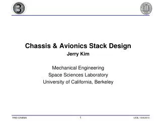
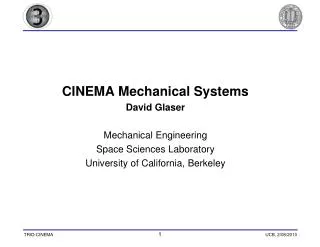
CINEMA Mechanical Systems David Glaser Mechanical Engineering Space Sciences Laboratory University of California, Berkeley. Mechanical Systems Agenda. AGENDA Exterior Structure (Spacecraft Chassis) Avionics Stack Structure Thermal Design Harnessing Design Each Section Will Include:

E N D
CINEMA Mechanical Systems • David Glaser • Mechanical Engineering • Space Sciences Laboratory • University of California, Berkeley
Mechanical Systems Agenda • AGENDA Exterior Structure (Spacecraft Chassis) Avionics Stack Structure Thermal Design Harnessing Design • Each Section Will Include: Overview Requirements Design <Test Results if any> Outstanding Issues Development Plan
Mechanical Systems - Exterior Structure Exterior Structure
Exterior Structure Design Top and Sides 5052-H32 Al Sheet Metal .048 inches thick Ends ¼ inch 6061 T6 Al 3U Corners will be hard anodized per CubeSat Specification All Dimensions Meet CubeSat Specification Cutouts for Mass Reduction – (May Be Eliminated for Radiation Shielding)
Exterior Structure Design Sheet Metal Parts Fastened Together with 4-40 Flathead Screws and PEM nuts PEM nuts will also be used in some places to fasten components to the chassis wall
Exterior Structure Design • CubeSat On-Off Switch Requirements • Remove-Before-Flight Pin Prevents Accidental Power Up • Deployment Switch • (Honeywell hermetically sealed switch) Closes When P-POD Door Opens
Exterior Structure Issues Unproven Chassis Design – To our knowledge, no other CubeSats have used this type of chassis and fastening method Possible Interference between PEM nuts and Avionics Stack Boards – TBD when all boards are specified – Screws and holes will be moved if there is interference Should mass reduction cutouts be used or not?
Exterior Structure Development Plans • Final Design Changes – February 2010 • In-House Fabrication By SSL Machine Shop March-April 2010 • Assemble and Test May 2010 • Test Integration with Spacecraft Components (Summer 2010) • Performance Test In Spacecraft Level Vibration Test (Fall 2010)
Mechanical Systems - Exterior Structure Avionics Structure
Avionics Structure Design • Available Stack Height: 145 mm • PC-104 Standard Connectors is 0.6 inch Space between boards • Each board is .06 inches thick *Non-standard board height
Avionics Structure Design • Seven PC-104 Boards Connected Via PC-104 Male –Female Standoffs • Electrical Connections via PC-104 Connector (Except HVPS board)
Avionics Structure Issues • Possible interference between components on PC-104 boards – need to map where higher components are on each board • If height limitation is surpassed, may need to move one or two batteries out of the stack
Avionics Structure Development Plans • Development • Evaluation of head and foot-room of board components February-March 2010 • In-House Fabrication of Parts by SSL Machine Shop, March-April 2010 • Integration with 7 PC-104 Boards (May? 2010) • Integration with CINEMA Chassis and harnessing (Summer 2010) • Performance Test In Spacecraft Level Vibration Test (Fall 2010)
Mechanical Systems - Exterior Structure Harnessing
Harnessing Overview Make electrical connections between avionics boards Make electrical connections between avionics stack and all instruments, and other components
Harnessing Requirements Few harnessing requirements have been defined
Harnessing Design • Design is mostly incomplete • What has been done: • MAGIC harness (between MAGIC board and sensor) has been designed and ETU built/tested (more info later) • Have begun discussions with John Sample on the HVPS board connector and its routing • Solar Panel to EPS connectors have been defined • Other?
Harnessing Issues • No known issues yet
Harnessing Development Plans • Development • Requirements should be developed – February 2010 • As the seven boards in the avionics stack become available a harnessing scheme will be worked out – February-April 2010 • Recommend meetings to discuss this begin immediately
Mechanical Systems - Thermal Thermal Design
Thermal Overview Thermal Design Approach is to create a simple model of the heat inputs and outputs through the satellite surface and critical instrument surfaces
Thermal Design • We have only just begun to make a thermal model of the satellite. Early approach: modify spreadsheet made for THEMIS by Dave Pankow • Model of tumbling spacecraft needed, in a addition to spinning at ecliptic-normal • Pankow did analysis of deployed magnetometer • Possible surfaces include black anodize, white paint, MLI • S-Band Transmitter and DC-DC converters both dissipate significant power – will be mounted to chassis wall
Thermal Analysis Results • Magnetometer Analysis – D. Pankow • Combination of white and black surfaces would create best temperature range • Harness may alter mag temperature by a few degrees • Stacer boom will be thermally isolated and have a moderate temperature range
Thermal Analysis Results • Spacecraft level model – no results yet, but note that upper and lower surfaces of satellite have large areas of aluminum wall exposed – careful choice of surface materials will be needed • S-Band Transmitter and DC-DC converters both dissipate significant power – will be mounted to chassis walls
Thermal Issues We have no thermal specifications for the patch antenna dielectric material (Rogers RT/Duroid 6002). For now we are treating it as a grey painted surface.
Thermal Development Plans • Lots of work ahead: • Spacecraft level model in Excel will be completed in early February • Need to include Earth IR emission • Need to include a tumbling mode • A thermal model and design of STEIN is needed to ensure that the detector remains as cool as possible • A thermal model of the torque coils is also warranted, as large temperature fluctuations would alter coil resistance and therefore magnetic dipole of the coils • All thermal models will be reviewed by Chris Smith, SSL thermal engineer • Thermal Desktop (FEA) models will be created if necessary
Mechanical Systems – Magnetometer Magnetometer Mechanical
Magnetometer Mechanical Overview Stacer boom (flight spare from FAST mission) Stowed Magnetometer
Magnetometer Mechanical Design Harness Design 18 Twisted Conductors 36 AWG Magnet Wire with Flight Heritage Aracon Braided Jacket – Silver/Nickel
Magnetometer Mechanical Design Mag Boom Design TiNi • Spans the width of the CINEMA chassis • Mounted to walls with screws • Mag extends out < 6.5 mm from outer wall
Magnetometer Mechanical Design Kickoff Spring Potted Sensor in housing
Magnetometer Mechanical Test Results • ETU Harness has been tested for insulation breakdown after extreme bending tests • Force Ratio on Pinpuller is 3.3 minimum. • ETU Mag Boom has been assembled with mock sensor mass and deployed 11 times • Students have successfully assembled it • Twice the release pin experienced binding and pin/bushing interface was redesigned and lubrication added – four consecutive successful deployments since redesign • Deployment forces on harness seem to be minimal • ETU Mass: 210 g (50 g more than requirement)
Magnetometer Mechanical Test Results Sample Test Video
Magnetometer Mechanical Issues • Binding of release pin • Will continue to monitor during subsequent tests • Need to define reliability requirement • Fragility of harness braided jacket • need to develop better handling procedures and reliability requirement • Boom length appears to be < 1 m (~0.90 m). MAGIC team has said this is fine as long as they know the exact deployed length • MAGIC team wants to assure that deployment shock will not exceed instrument limitations • Thermal design needs to be finalized – surface materials (mentioned earlier in Thermal presentation)
Magnetometer Mechanical Development Plans • Development • Deployment shock test with STM supplied by MAGIC team – spring 2010 • Possible Vibe Test (Piggyback on RBSP test) Feb-March 2010 • Fabrication of Flight Model Parts – April-May 2010 • Integration with CINEMA Chassis (Summer 2010) • Performance Test In Spacecraft Level Vibration and Thermal Vac Tests (Fall 2010)
Mechanical Systems - STEIN STEIN Mechanical David Glaser
STEIN Mechanical Design Baffles and housing interior are blackened
STEIN Mechanical Design STEIN Assembly Attenuator Mechanism is Modular
STEIN Mechanical Design Electrostatic Deflector 30 .002-inch thick BeCu blades sandwiched between .025-inch thick Aluminum clamps Blades are Cu plated and blackened with Ebanol C
STEIN Mechanical Test Results • Mass of ETU Sensor Head: ~250 g (meets requirement) • Attenuator is easily mounted to and removed from housing • Deflection plates mount easily into housing • Original deflectors scattered many electrons - redesigned • No HV arcing was observed in vacuum chamber tests with original deflectors • New deflectors have been assembled but not yet tested
STEIN Mechanical Design New Electrostatic Deflector Design 30 .002-inch thick BeCu blades sandwiched between .025-inch thick Aluminum clamps Blades are Cu plated and blackened with Ebanol C
STEIN Mechanical Design Electrostatic Deflector Old Flat Plate Design New design is wider to eliminate edge effects