
Interrupts
E N D
Presentation Transcript
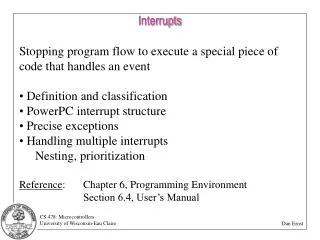
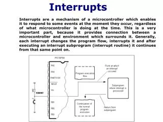
Interrupts Interrupts are a mechanism of a microcontroller which enables it to respond to some events at the moment they occur, regardless of what microcontroller is doing at the time. This is a very important part, because it provides connection between a microcontroller and environment which surrounds it. Generally, each interrupt changes the program flow, interrupts it and after executing an interrupt subprogram (interrupt routine) it continues from that same point on.
TÉCNICA DE POLLING Por lo regular la técnica utilizada para la lectura de entradas al microcontrolador, como por ejemplo pulsadores, ha consistido en una comprobación cíclica por parte del programa de estado de la entrada correspondiente, a esta técnica se le conoce como Polling o «por sondeo». INTERRUPCIONES Una interrupción consiste en un mecanismo por el cual un evento interno o externo puede interrumpir la ejecución de un programa en cualquier momento. A partir de entonces se produce automáticamente un salto a una subrutina de tratamiento de la interrupción, ésta atiende inmediatamente el evento y retorna luego a la ejecución del programa exactamente donde estaba en el momento de ser interrumpido, continuando su tarea justo donde la dejó.
La interrupción tiene la característica de la inmediatez, nace de la necesidad de ejecutar una subrutina en el momento preciso y, por tanto, se considera su intervención urgente. Este método es más eficaz que la técnica de Polling ya que el microcontrolador no perderá el tiempo preguntando a la línea de entrada para leer el estado, sino que únicamente atenderá al periférico cuando esto se lo pida mediante la solicitud de interrupción. Las interrupciones constituyen el mecanismo más importante para la conexión del microcontrolador con el exterior
TIPOS DE INTERRUPCIONES • El PIC16F84 dispone de 4 posibles fuentes de interrupciones: • Interrupción INT. Se provoca por la activación del pin RB0/INT • Interrupción RBI. Se provoca por el cambio de estado en una o varias de las 4 líneas de más peso RB7:RB4 del puerto B • Interrupción T01. Se provoca por desbordamiento del Timer 0 • Interrupción EE1. Se provoca por la finalización de la escritura en la EEPROM de datos. • FUNCIONAMIENTO DE UNA INTERRUPCIÓN • Cuando se produce cualquiera de los sucesos indicados anteriormente se origina una petición de interrupción que, si se acepta, origina el siguiente mecanismo hardware: • Salva el valor actual del contador de programa (PC) guardando su contenido en la pila • El bit GIE (Global Interrupt Enable) del registro INTCON es puesto a cero, lo que prohibe cualquier otra interrupción • El PC se carga con el valor 004h, que es la posición del vector de interrupción • Comienza a ejecutarse el programa de atención a la interrupción que se encuentra a partir de la dirección 004h.
Los bits de control localizados en el registro INTCON habilitan y configuran las interrupciones. Cada causa de interrupción actúa con dos flags representados en la siguiente figura: Existe un único vector de interrupción en la dirección 04h. Sea cual sea la interrupción, el contador de programa se carga con la dirección 004h, figura 17-2(b). A continuación debe de comprobar los diferentes indicadores para saber cuál es el dispositivo que produce la interrupción y actuar según sea el caso. En el PIC16F84 las interrupciones se comportan casi exactamente igual que las subrutinas. Desde el punto de vista del control del programa, una interrupción conduce el mismo efecto que ocurriría si el programa tuviese un “call 004h” en el punto en que se produjo la interrupción, ejecutando la subrutina de atención de interrupción.
BANDERAS RELACIONADAS CON INTERRUPCIÓN Las banderas relacionadas con las interrupciones se alojan en los registros INTCON y OPTION. EL REGISTRO INTCON El registro INTCON (Interrupts Control Register) es el registro para el control de las interrupciones , está localizado en la dirección 0Bh del Banco 0 ó 8bH del Banco. Es el encargado del manejo de las interrupciones y contiene los 8 bits que se muestran en la siguiente tabla, de los cuales unos actúan como banderas señaladoras del estado de la interrupción y otros como bit de permiso o autorización para que se pueda producir la interrupción.
Interrupts Bit 7 GIE (Global Interrupt Enable bit). Bandera de habilitación global del permiso de interrupción. Se borra automáticamente cuando se reconoce una interrupción para evitar que ninguna otra se produzca mientras se está atendiendo a la primera. Al retornar de la interrupción con una instrucción retfie, el bit GIE se vuelve a activar poniéndose a “1”. Para el resto de las banderas no se ha previsto mecanismo de interrupción, por lo que el programa de atención a la interrupción debe realizar el tratamiento de la correspondiente interrupción y además debe poner el o las banderas de indicación de interrupción a “0”. Bit which enables or disables all interrupts.1 = all interrupts are enabled0 = all interrupts are disabled Bit 6 EEIE (EEPROM Write Complete Interrupt Enable bit) Bit which enables an interrupt at the end of a writing routine to EEPROM1 = interrupt enabled0 = interrupt disabledIf EEIE and EEIF (which is in EECON1 register) are set simultaneously , an interrupt will occur. bit 5 T0IE (TMR0 Overflow Interrupt Enable bit) Bit which enables interrupts during counter TMR0 overflow.1 = interrupt enabled0 = interrupt disabledIf T0IE and T0IF are set simultaneously, interrupt will occur. bit 4 INTE (INT External Interrupt Enable bit) Bit which enables external interrupt from pin RB0/INT.1 = external interrupt enabled0 = external interrupt disabledIf INTE and INTF are set simultaneously, an interrupt will occur. bit 3 RBIE (RB port change Interrupt Enable bit) Enables interrupts to occur at the change of status of pins 4, 5, 6, and 7 of port B. 1 = enables interrupts at the change of status0 =interrupts disabled at the change of statusIf RBIE and RBIF are simultaneously set, an interrupt will occur.
Interrupts bit 2 T0IF (TMR0 Overflow Interrupt Flag bit) Overflow of counter TMR0.1 = counter changed its status from FFh to 00h0 = overflow did not occurBit must be cleared in program in order for an interrupt to be detected. bit 1 INTF (INT External Interrupt Flag bit) External interrupt occurred.1 = interrupt occurred0 = interrupt did not occurIf a rising or falling edge was detected on pin RB0/INT, (which is defined with bit INTEDG in OPTION register), bit INTF is set. bit 0 RBIF (RB Port Change Interrupt Flag bit) Bit which informs about changes on pins 4, 5, 6 and 7 of port B.1 = at least one pin has changed its status0 = no change occurred on any of the pinsBit has to be cleared in an interrupt subroutine to be able to detect further interrupts.
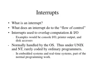
Interrupts PIC16F84 has four interrupt sources:1. Termination of writing data to EEPROM2. TMR0 interrupt caused by timer overflow3. Interrupt during alteration on RB4, RB5, RB6 and RB7 pins of port B.4. External interrupt from RB0/INT pin of microcontrollerGenerally speaking, each interrupt source has two bits joined to it. One enables interrupts, and the other detects when interrupts occur. There is one common bit called GIE which can be used to disallow or enable all interrupts simultaneously. This bit is very useful when writing a program because it allows for all interrupts to be disabled for a period of time, so that execution of some important part of a program would not be interrupted. When instruction which resets GIE bit was executed (GIE=0, all interrupts disallowed), any interrupt that remained unsolved should be ignored. Interrupts which remained unsolved and were ignored, are processed when GIE bit (GIE=1, all interrupts allowed) would be cleared. When interrupt was answered, GIE bit was cleared so that any additional interrupts would be disabled, return address was pushed onto stack and address 0004h was written in program counter - only after this does replying to an interrupt begin! After interrupt is processed, bit whose setting caused an interrupt must be cleared, or interrupt routine would automatically be processed over again during a return to the main program.
Keeping the contents of important registers Only return value of program counter is stored on a stack during an interrupt (by return value of program counter we mean the address of the instruction which was to be executed, but wasn't because interrupt occurred). Keeping only the value of program counter is often not enough. Some registers which are already in use in the main program can also be in use in interrupt routine. If they were not retained, main program would during a return from an interrupt routine get completely different values in those registers, which would cause an error in the program. One example for such a case is contents of the work register W. If we suppose that main program was using work register W for some of its operations, and if it had stored in it some value that's important for the following instruction, then an interrupt which occurs before that instruction would change the value of work register W which would directly be influenced the main program.Procedure of recording important registers before going to an interrupt routine is called PUSH, while the procedure which brings recorded values back, is called POP. PUSH and POP are instructions with some other microcontrollers (Intel), but are so widely accepted that a whole operation is named after them. PIC16F84 does not have instructions like PUSH and POP, and they have to be programmed.
Keeping the contents of important registers Due to simplicity and frequent usage, these parts of the program can be made as macros. The concept of a Macro is explained in "Program assembly language". In the following example, contents of W and STATUS registers are stored in W_TEMP and STATUS_TEMP variables prior to interrupt routine. At the beginning of PUSH routine we need to check presently selected bank because W_TEMP and STATUS_TEMP are found in bank 0. For exchange of data between these registers, SWAPF instruction is used instead of MOVF because it does not affect the STATUS register bits.Example is an assembler program for following steps:1. Testing the current bank2. Storing W register regardless of the current bank3. Storing STATUS register in bank 0.4. Executing interrupt routine for interrupt processing (ISR)5. Restores STATUS register6. Restores W registerIf there are some more variables or registers that need to be stored, then they need to be kept after storing STATUS register (step 3), and brought back before STATUS register is restored (step 5).
External interrupt on RB0/INT pin of microcontroller External interrupt on RB0/INT pin is triggered by rising signal edge (if bit INTEDG=1 in OPTION<6> register), or falling edge (if INTEDG=0). When correct signal appears on INT pin, INTF bit is set in INTCON register. INTF bit (INTCON<1>) must be cleared in interrupt routine, so that interrupt wouldn't occur again while going back to the main program. This is an important part of the program which programmer must not forget, or program will constantly go into interrupt routine. Interrupt can be turned off by resetting INTE control bit (INTCON<4>). Possible application of this interrupt could be measuring the impulse width or pause length, i.e. input signal frequency. Impulse duration can be measured by first enabling the interrupt on rising edge, and upon its appearing, starting the timer and then enabling the interrupt on falling edge. Timer should be stopped upon the appearing of falling edge - measured time period represents the impulse duration.
Interrupt during a TMR0 counter overflow Overflow of TMR0 counter (from FFh to 00h) will set T0IF (INTCON<2>) bit. This is very important interrupt because many real problems can be solved using this interrupt. One of the examples is time measurement. If we know how much time counter needs in order to complete one cycle from 00h to FFh, then a number of interrupts multiplied by that amount of time will yield the total of elapsed time. In interrupt routine some variable would be incremented in RAM memory, value of that variable multiplied by the amount of time the counter needs to count through a whole cycle, would yield total elapsed time. Interrupt can be turned on/off by setting/resetting T0IE (INTCON<5>) bit.
Interrupt upon a change on pins 4, 5, 6 and 7 of port B Change of input signal on PORTB <7:4> sets RBIF (INTCON<0>) bit. Four pins RB7, RB6, RB5 and RB4 of port B, can trigger an interrupt which occurs when status on them changes from logic one to logic zero, or vice versa. For pins to be sensitive to this change, they must be defined as input. If any one of them is defined as output, interrupt will not be generated at the change of status. If they are defined as input, their current state is compared to the old value which was stored at the last reading from port B.
Interrupt upon finishing write-subroutine to EEPROM This interrupt is of practical nature only. Since writing to one EEPROM location takes about 10ms (which is a long time in the notion of a microcontroller), it doesn't pay off to a microcontroller to wait for writing to end. Thus interrupt mechanism is added which allows the microcontroller to continue executing the main program, while writing in EEPROM is being done in the background. When writing is completed, interrupt informs the microcontroller that writing has ended. EEIF bit, through which this informing is done, is found in EECON1 register. Occurrence of an interrupt can be disabled by resetting the EEIE bit in INTCON register.
In order to use an interrupt mechanism of a microcontroller, some preparatory tasks need to be performed. These procedures are in short called "initialization". By initialization we define to what interrupts the microcontroller will respond, and which ones it will ignore. If we do not set the bit that allows a certain interrupt, program will not execute an interrupt subprogram. Through this we can obtain control over interrupt occurrence, which is very useful. The above example shows initialization of external interrupt on RB0 pin of a microcontroller. Where we see one being set, that means that interrupt is enabled. Occurrence of other interrupts is not allowed, and interrupts are disabled altogether until GIE bit is set to one.
Interrupt initialization The following example shows a typical way of handling interrupts. PIC16F84 has got a single location for storing the address of an interrupt subroutine. This means that first we need to detect which interrupt is at hand (if more than one interrupt source is available), and then we can execute that part of a program which refers to that interrupt.