Download
1 / 43
510 likes | 1.33k Vues
INTRODUCTION TO THE RADAR. ELC 451L. WHAT IS RADAR?. RADAR Stands for R adio D etection A nd R anging 2. RADAR can operate in: Darkness Haze Fog Rain or Snow. AIRPORT RADAR SYSTEM. RADAR SYSTEM. RADAR SPECIFICATIONS. RADAR BLOCK DIAGRAM. TRANSMITTER. 1. Functions:

E N D
INTRODUCTION TO THE RADAR ELC 451L
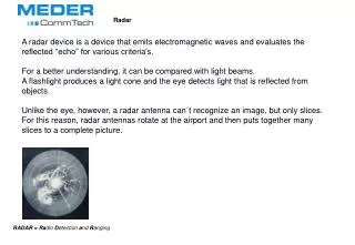
WHAT IS RADAR? • RADAR Stands for Radio Detection And Ranging 2. RADAR can operate in: DarknessHazeFogRain or Snow
TRANSMITTER • 1. Functions: • Creates the radio wave to be transmitted • Conditions the wave to form the pulse train. • Amplifies the signal to a high power level to provide adequate range. • 2. Sources of Carrier Wave: • Klystron, • Traveling Wave Tube (TWT) • Magnetron.
RECEIVER • Functions of Receiver: • Detects the received signal • Amplifies the returned signal. • Basic Characteristic: • In order to provide the greatest range, the receiver must have a high signal-to-noise ratio (S/N).
POWER SUPPLY • Function of Power Supply: • Provides the electrical power for all the components. • Power Requirement by Transmitter: • The transmitter is the largest consumer of power is , which may require several kW of average power. • The actually power transmitted in the pulse may be much greater than 1 kW. • Usually only average amount of power consumed is provided , not the high power level during the actual pulse transmission. • Energy is often stored in a capacitor bank, during the rest time. • The stored energy then can be put into the pulse when transmitted, increasing the peak power.
SYNCHRONIZER • Function of the Synchronizer: • Regulates that rate at which pulses are sent (i.e. sets PRF) • Resets the timing clock for range determination for each pulse.
DUPLEXER SWITCH • Purpose of Duplexer: • To protect the receiver from the high power output of the transmitter. • A duplexer is not required if the transmitted power is low.
ANTENNA Function of Antenna: • Transmit pulses • Focus the energy into a well-defined beam. • Keep track of its own orientation by using a synchro-transmitter or phased array system.
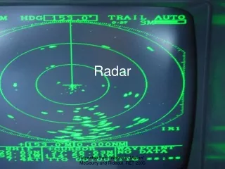
DISPLAY • Types of Radar Displays: • A-Scan (Amplitude vs Time) – No information on direction of target • Plan Position Indicator – Displayed in the same relative direction as the antenna.
DETERMINATION OF SIGNAL STRENGTH In Search RADAR Systems where the antenna moves continuously, maximum echo is determined by the detection circuitry.
RANGE RESOLUTION • Refers to the ability of a Radar system to distinguish between two or more targets on the same bearing but different ranges. • A well designed radar system, will all other factors at maximum efficiency should be able to distinguish targets separated by ½ of the Pulse Width (PW), i.e
BEARING RESOLUTION • Refers to the ability of a radar system to distinguish targets at the same range but different bearings. • Degree of range bearing depends on: 1. Radar beam width 2. Range of targets
RADAR APPLICATIONS • Navigational aids and surveillance of enemy aircrafts in military applications • Air traffic control as primary and secondary radars • Weather radars • Law enforcement as radar speed meters • Games for measuring speed of balls, etc.
HALF-POWER POINTS 1. When all half-power points are connected to the antenna by a curve, the curve is called the Antenna Beam Width. 2. Two targets at the same range must be separated by at least one beam width so as to be distinguished from one another.
TRAVELLING WAVE TUBE • A traveling-wave tube (TWT)used to amplify microwave signals to high power, usually in an electronic assembly known as a traveling-wave tube amplifier (TWTA). • The bandwidth of a broadband TWT can be as high as one octave, although tuned (narrowband) versions exist. • Operating frequencies range from 300 MHz to 50 GHz. • The voltage gain of a TWT can be of the order of 70 decibels
THE TRAVELLING WAVE TUBE • A traveling-wave tube (TWT)used to amplify microwave signals to high power, usually in an electronic assembly known as a traveling-wave tube amplifier (TWTA). • The bandwidth of a broadband TWT can be as high as one octave, although tuned (narrowband) versions exist. • Operating frequencies range from 300 MHz to 50 GHz. • The voltage gain of a TWT can be of the order of 70 decibels
TWT- HISTORY • In December 1943 the first tube gave again of about 8 dB at a 9.1 cm wavelength, with a 13 dB noise figure. The work was later transferred to the Clarendon Laboratory, Oxford. • Much of the mathematical analysis of TWT operation was developed by John R. Pierce, of Bell Labs. • Nowadays, TWTS are by far the most widely-used of microwave tubes, and are employed extensively in communication and radar systems. • They are especially suited to airborne applications, where their small size and low weight are valuable.
TWT – THEORY (1) • Electrons from a heated cathode are accelerated towards the anode, which is held at a high positive potential with respect to the cathode, and a proportion pass through a hole in the anode to produce the beam. • To achieve good focussing by this method requires a very large magnetic field, which can mean a bulky, heavy magnet. The arrangement usually employed is called periodic permanent magnet (PPM) focussing, in which a number of toroidal permanent magnets of alternating polarity is arranged along the tube. • This arrangement reduces enormously the required weight of magnet (under ideal conditions by a factor 1/N2; where N is the number of magnets used).
TWT – THEORY (2) • The velocity, v, of an electron beam is given by: • An anode voltage of 5 kV gives an electron velocity of 4.2 x 10⁷ m/s. The signal would normally travel at c, the velocity of light (3x10⁸ m/s), which is much faster than any 'reasonable' electron beam. • If the signal can be slowed down to the same velocity as the electron beam, it is possible to obtain amplification of the signal by virtue of its interaction with the beam.
TWT: SLOWING OF SIGNAL • Slowing is usually achieved using the helix electrode, which is simply a spiral of wire around the electron beam. • Without the helix, the signal would travel at a velocity c. With the helix, the axial signal velocity is approximately c x (p /2πa) where a, p are as shown on the left. • By proper selection of a and p, the signal can be slowed. 4. The condition for equal slow-wave and electron-beam velocities is therefore approximately:
TWT AMPLIFICATION • The interaction between the beam and the slow wave takes the form of 'velocity modulation' of the beam (i.e some electrons are accelerated and some retarded) forming electron bunches within the beam. • The beam current becomes modulated by the RF signal, and the bunches react with the RF fields associated with the slow wave travelling down the helix, resulting in a net transfer of energy from the beam to the signal, and consequent amplification.
KLYSTRON AMPLIFIER • Used as amplifiers at microwave and radio frequencies to produce both low-power reference signals for radar receivers and to produce high-power carrier waves for communications.
RADAR MODULATORS • Radar modulators Control the following: 1. the RF energy to be produced 2. The Repetition frequency 3. Shape of the pulse. • There are two types of radar modulators: 1. Anode Modulator 2. Grid Modulator
BLOCK DIAGRAM OF RADAR MODULATOR • Purpose of the Charging Impedance: • To restrict the rate at which energy is delivered to the storage devices • To Prevent the dissipation of energy through the Source during the discharge period.
2Vs Vs Charging Current Delay Line 150V +ve Trigger DC Shield Oscillating Device e.g. Magnetron LINE-TYPE MODULATOR (1) A line-type modulator contains a gas tube and a delay line as the energy storage element.
2Vs Vs Charging Current Delay Line 150V +ve Trigger DC Shield Oscillating Device e.g. Magnetron LINE-TYPE MODULATOR (2)
CHARGING CURVE OF THE PFN IN A LINE TYPE MODULATOR Uo The inductance of the charging coil offers a large inductive resistance to the current and builds up a strong magnetic field.