Download

1 / 25
250 likes | 428 Vues
Why Use the UG Model for Dimensional Control. George Kovatchev Sitius Automation. UG Users Group Conference Fall 2000. SITIUS. About us. Sitius Automation develops process oriented solutions that are fully integrated in commercial CAD systems We are Unigraphics Alliance Partner

E N D
Why Use the UG Model for Dimensional Control George KovatchevSitius Automation UG Users Group ConferenceFall 2000 SITIUS
About us • Sitius Automation develops process oriented solutions that are fully integrated in commercial CAD systems • We are Unigraphics Alliance Partner • We specialize in dimensional metrology SITIUS
Who needs CMM inspection • Die designer – verify the tool against the part • NC programmer / CNC operator – improve the cutting process • Tooling engineer – make corrections to compensate for casting deformations • QC manager – conform to company standards • Production technologist – maintain stable process • Assembly group – save time fitting • CMM operator – overtime, teach the engineers GD&T • The boss – keep the customer happy • INSURANCE SITIUS
Preventive and Corrective Use Identify cutter deflection Best-fit EDM electrodes Correct casting locators SITIUS
How it’s done Geometry 2D Drawings 3D Cad Model Manual CMM Program Part Verification CMM Program SITIUS
How 2D compares to 3D • (+) No need to buy new CMM software • (-) Very difficult to inspect free-form surfaces • (-) Need to maintain 2D drawings • (-) Low reproducibility • (-) Increased chance of errors • (-) Hard to keep up with engineering changes SITIUS
How manual inspection compares to off-line programming • (+) Highly adaptive • changes in setup • missing features • on-the-floor inspection • changes in requirements • (+) Faster turnaround on low volume • tooling, inserts • EDM electrodes • prototyping • first article inspection SITIUS
How manual inspection compares to off-line programming • (+) Works with manual machines • CMM’s • Laser trackers • Articulating arms • (+) Easier to perform • (-) Increased chance of errors* • (-) Reduced repeatability and reproducibility* • (-) Requires operator • (-) Higher demand for CAD based solutions SITIUS
2D vs. 3D To CAD model - 30 minutesFrom 2D drawings - never From 2D drawings - 3 daysTo CAD model - 4 hours SITIUS
2D Drawings vs. 3D CAD Models • Faster - sometimes by order of magnitude • Inspect any part • Increased repeatability and reproducibility • Reduced data duplication • Better way to inspect mechanical parts regardless of the method (manual or off-line programming) SITIUS
Are all CAD based inspections equal? NO • Access to the math data • Integration between CAD/CAM/Inspection • Accuracy, performance and usability • Other factors SITIUS
Comparison by interface to CAD • IGES, VDA-FS, STEP, DXF • Most of the commercial systems use IGES • Parasolid • Maybe one • Direct links • Some promise, none really work • Integrated • Two for Unigraphics SITIUS
Time to start work • IGES - from 5 min to 5 days • Parasolid - from 5 to 20 min • Direct link - should be fast • Integrated - from 1 to 2 min SITIUS
Accuracy and reliability • IGES - low • Parasolid - high • Direct link - depends if there is a translation • Integrated - 100% SITIUS
Example of IGES translation Nominal points generated by the “industry leader” in CAD based inspection are compared with the actual Unigraphics CAD model. The CMM software uses IGES to translate the part. The profile tolerance is 0.100 mm (actual part needs to be between the red and the blue line). In effect the nominal hits are off from -0.053mm up to -0.111mm, well below the lower tolerance limit of -0.050 mm resulting in significant errors and repeated rework on the part. SITIUS
Back to Unigraphics The same part checked in Unigraphics before and after best fit. SITIUS
Avoiding data duplication - is it important? • Waste of time • Source of errors • Engineering changes • Concurrent engineering SITIUS
Data duplication • 2D Drawings - Yes • IGES - Yes • Parasolid - Yes • Direct link - Usually • Integrated - No if using User Defined Objects (UDO) SITIUS
Other benefits of using an integrated solution for CAD based inspection • Access to solid information - very important for part verification and probe radius compensation • Support for assemblies • Graphical reporting and simulation • Support for embedded GD&T • Smart updates • Macros, Parameters, Undo SITIUS
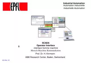
CAD based simulation SITIUS
Reporting Actual color-coded results GD&T reporting SITIUS
Updates SITIUS
Ability to work in 3D Accuracy and reliability Notification of changes Eliminate data duplication Concurrent engineering Summary
If you design your part in Unigraphics inspect it there as well. This is your last step before you ship the part out. Do it right! Do yourself a favor
Thank you! Please join us for a demonstration. • on the web at http://www.sitius.com • e-mail georgek@sitius.com SITIUS Contact Us... SITIUS