Advanced Cluster and Pad Structure for HBD+TPC Configuration Studies
Explore the impact of zero field on pad shape, cluster rejection, and blob characteristics in the HBD+TPC scheme for efficient event reconstruction and particle ID. Analyze cluster amplitude and optimize pad size based on blob separation and amplitude information. Discuss simulation and reconstruction algorithms, magnetic field compensation, and background suppression strategies for reliable HBD operation.

Advanced Cluster and Pad Structure for HBD+TPC Configuration Studies
E N D
Presentation Transcript
HBD pad structure. (based on old studies) Sasha Milov Nov 19, 2003
Outline • Zero field: • Pad shape and size • Cluster shapes and rejection • HBD+TPC configuration: • Blob shape • Occupancy • First attempts to do PID • Next step: • Choices
Zero field • Pad size about size of the blob: • Separation: • Based on the shape: • SPLIT • NONCOMPACT • COMPACT • Amplitude information: • Just geometry is insufficient, amplitude information is required • Requirements: • Smaller that the blob size • Large enough to get as much signal as possible and lower the gain • Signal / to noise (electronics driven issue) • Total number of channels is not a driving factor
Zero field • Cluster amplitude analysis is essential: • Geometry itself cannot do the job, the limiting factor is the blob size, not the cluster size: charge 0 4 8 Distance between blobs (cm)
HBD+TPC scheme, residual field • HIJING central event (no acceptance cuts) • Using PISA with • HBD in • New Si detector in • Nose cones in • Compensated magnetic field • Existing PHENIX out • Using pisaRootRead • Using “unfolding” of the electron tracks: • Particle tracks is broken into entries to HBD • Photoelectrons are assigned to a particular entry based of ToF. • Remaining problems: • Mylar membranes • ~1% of p.e. are lost in this procedure due to ambiguities entry 2 entry 1 entry 4 entry 3 3
What does an event look like? East West 200 GeV Au-Au central event “unfolded” detector only electrons shown points - charged particles Green - all electrons Blue - electrons from the first entry Red - and from the vertex 7
Blob shape Red e+Blue e- (0,0) is the particle hit position on HBD Z – unchanged Y – pT dependent No strong hit position dependence 9
Blob shape Blob shape is pT dependent, however, most of particles are localized within 2-2.5cm from the center of the blob 10
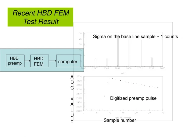
Slow Simulator • Geometry: • Hexagonal pads provide less signal sharing • Photoelectron belongs to one pad* • Detector response: • Photoelectron produces exponent signals • Photoelectron from scintillation are proportional to N hits in HBD* and are coming at the beginning of the event* nonuniformly* in Z. • Charged particle are assumed to be m.i.p.’s*, and their signal is proportional to the number of primary clusters in a thing layer. Each cluster produces* more than a single electron. • Gain and noise are fixed*. Q.E. is 80%. • Electronics response: • ~40ns bipolar shaper *. • Leading edge discriminator. • Constant gain and noise* * Can be improved 11
Slow Simulator • Reconstruction algorithm: • Build clusters of pads • Optimize for the best performance in “real” environment* • Keep track of ancestry information of the particles producing hits (up to 3 contributors to each cluster including charged particles, scintillation and noise). • Things to be implemented: • Cluster splitting • Timing properties of the clusters • More thinking • Questions to be answered: • Get reliable reconstruction algorithm. • Pad size and shape? • Magnetic field optimization? • What background suppression / signal efficiency can we achieve? • What do we do with less number of photoelectrons? the Goal: Prove that the HBD can work! 12
HBD Event Red are fired cells, blue are cells with low amplitude, green are cells which fired late 13
What clusters look like? • Cluster parameters are within expectations • They don’t like the same as without the field and noise (did anybody expected them to?) • A lot more can be done to tune clustering algorithm Noise+ Single Double No pT cut used 15
Particle ID story • So one can reject pions quite efficiently even with the first shot. • But the problem is not there, it’s in the number of electrons themselves 16
What does it look like without Si? East West 1 layer of SVD instead of 4 8
Next • It depends where we go. • The fact that even with rather strong magnetic field we could do something tells that the concept is fine. • What is the optimal pad size? • Definitely start with the (<~) blob size. • Than, if the field in the new configuration is too strong, go >50% of the size. • If fails, then try a single electron detection (very small pads) • Clustering: • Has to be done VERY carefully • First involving simulation, then tuning to the data / prototype / on-line • Do not be afraid if a cluster needs be compared to a 100x100x100 look-up table to find its best solution of 2 vs. 1 electron.