Download
1 / 29
300 likes | 380 Vues
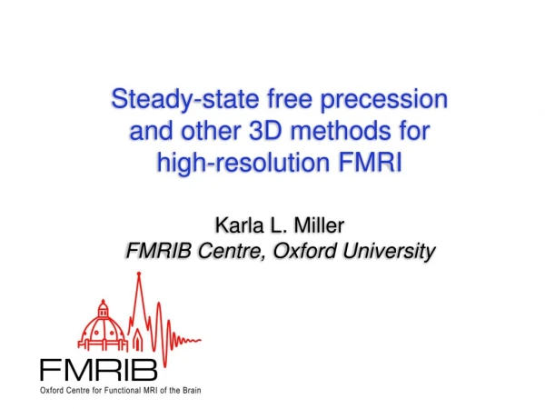
Steady-state free precession and other 3D methods for high-resolution FMRI. Karla L. Miller FMRIB Centre, Oxford University. Why is high-resolution FMRI so difficult?. Signal-to-noise ratio: For example, 2x2x2 mm has 8x SNR of 1x1x1 mm (would require 64 times longer scan)

E N D
Steady-state free precession and other 3D methods for high-resolution FMRI Karla L. Miller FMRIB Centre, Oxford University
Why is high-resolution FMRI so difficult? • Signal-to-noise ratio: • For example, 2x2x2 mm has 8x SNR of 1x1x1 mm (would require 64 times longer scan) • For single-shot, distortion increases with matrix size • Isotropic resolution (thin slices) is hard in 2D
Segmented EPI [McKinnon MRM 1993] 7T, 2D segmented EPI 0.5 x 0.5 x 3 mm3 [Yacoub et al MRM 2003] 2D High-resolution FMRI Acquire EPI in multiple shots (“segmented” or “interleaved”) Allows increased resolution without increased distortion High-resolution in-plane, but limit on slice thickness!
t1 t2 t3 t4 t5 t6 2D Multi-slice MRI excited slice Each slice excited & acquired separately TR: time between repeated excitation of same slice (typically 1–3 seconds) Slices no thinner than ~1 mm
excited volume “True” 3D imaging excited volume Excite entire slab, readout in 3D k-space TR: time between repeated slab excitations (5-50 ms) Can achieve thin slices (isotropic resolution, like structurals)!
SNR Benefit of 3D Trajectories SNR is higher for 3D since same magnetization is sampled more frequently Calculated for 3D stack-of-spirals [Yanle Hu and Gary Glover, Stanford]
3D Functional MRI • Advantages: • SNR benefits, provided short TR can be used • Can achieve thinner slices (e.g., for “isotropic” voxels) • 3D multi-shot low distortion • Disadvantages: • Can require long volume scan times (may be fixable!) • Acquisition time (e.g., “slice timing”) is difficult to define • Slices must be contiguous (no inter-slice gap)
3D stack-of-EPI [Irarrazabal et al, MRM 1995] Adapting echo planar imaging (EPI) to 3D 2D segmented EPI
3D EPI GRE at 3T 0.8 x 0.8 x 0.8 mm3 = 0.5 mm3 TR=69 ms, 7 s/vol, 24 minutes scan time
3D EPI GRE at 3T (0.8 x 0.8 x 0.8 mm3 ) Single image 7 s scan time Mean timecourse image 4 min scan time
Adapting spiral to 3D 2D interleaved spiral 3D stack-of-spiral [Yang et al, MRM 1996]
Comparison of 2D vs 3D spiral FMRI • 20% higher functional SNR in 3D compared to 2D • Significantly more activated voxels (2x at chosen threshold) [Hu and Glover, MRM 2006]
full k-space partial k-space 3D spiral GRE with partial k-space • Faster imaging: 64 slices in 6.4 s (full) vs. 4.0 s (partial) • Higher statistical power due to reduced physiological noise [Hu and Glover, MRM 2006]
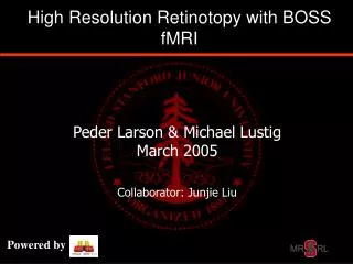
High-resolution retinotopy at 7T 2D single-shot EPI 3D segmented EPI • 1x1x1 mm3 resolution • Identification of retinotopically-distinct regions • Reduced distortion in 3D segmented EPI Itamar Kahn and Randy Buckner, MGH
3D GRE BOLD at 7T 0.67 x 0.67 x 0.67 mm3 = 0.3 mm3 12 minutes scan time Karla Miller and Chris Wiggins, MGH
3D GRE BOLD at 7T 0.58 x 0.58 x 0.58 mm3 = 0.2 mm3 18 minutes scan time Karla Miller and Chris Wiggins, MGH
3D Imaging: GRE vs. SSFP • 3D imaging generally requires short TR • SSFP tends to out-perform GRE in this regime
Bowen 2005 Miller 2003 Scheffler 2001 SSFP image Field map Balanced Steady-state Free Precession (SSFP) • SSFP signal dependence on off-resonance • Transition band SSFP: image in signal transitions • Contrast: deoxyHb frequency shift • Passband SSFP: image in flat part of signal profile • Contrast: T2 at short TR
Transition-band SSFP Functional contrast occurs in “bands” • Changing center frequency shifts region of high signal (and functional contrast) Multi-frequency experiments • Repeat stimulus at multiple center frequencies to extend coverage • Combine data into single activation map
3D Spiral transition-band SSFP at 1.5T 1 x 1 x 2 mm3, 3D spiral, standard head coil Courtesy Jongho Lee, Stanford University
3D EPI tbSSFP at 3T 0.8 x 0.8 x 0.8 mm3 = 0.5 mm3 TR=35 ms, 8.3 s/vol, 24 minutes scan time
3D EPI tbSSFP FMRI at 7T 0.75 x 0.75 x 0.75 mm3 = 0.4 mm3 22 minutes scan time Collaboration with Chris Wiggins, MGH
Physiological noise: transition-band SSFP Compared to GRE, higher physiological noise in tbSSFP Poor fit with standard physiological noise model
Image Data 0+ Real-time computer FID Reducing physiological noise in SSFP Respiration modulates frequency = shift in SSFP bands Real-time feedback to compensate for frequency drift [Jongho Lee et al, MRM 2006]
Dynamic frequency tracking compensation off compensation on [Jongho Lee et al, MRM 2006]
o GRE x SSFP Passband SSFP vs. GRE (3T) GRE pbSSFP TE= 3 ms TE= 25 ms
Physiological noise: passband SSFP Short TR (6-12 ms) Compared to GRE, lower physiological noise in pbSSFP
Conclusions • Why 3D for high-resolution FMRI? • High-res multi-shot short TR 3D • Lower distortion with short, 3D readouts • Can achieve isotropic resolution (thin slices) • Challenges and advances • Efficient 3D versions of both EPI and spiral trajectories • Volume acquisition times: Speed up with partial k-space (or parallel imaging) • SSFP FMRI • New method for FMRI contrast • Highly suitable to 3D due to short TR
FMRIB, Oxford Stephen Smith Peter Jezzard Stanford John Pauly Jongho Lee Yanle Hu Gary Glover Acknowledgements Martinos Centre, MGH Christopher Wiggins Graham Wiggins Itamar Kahn Funding:NIH, GlaxoSmithKline, EPSRC, Royal Academy of Engineering Related work: #357 SSFP analysis (Th-AM), #272 SSFP modeling (Th-PM)