A 150-MHz Graphics Rendering Processor with 256-Mb Embedded DRAM
100 likes | 106 Vues
A 150-MHz Graphics Rendering Processor with 256-Mb Embedded DRAM

A 150-MHz Graphics Rendering Processor with 256-Mb Embedded DRAM
E N D
Presentation Transcript
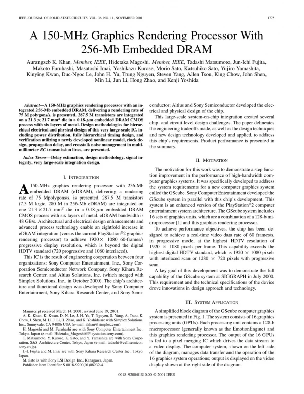
IEEE JOURNAL OF SOLID-STATE CIRCUITS, VOL. 36, NO. 11, NOVEMBER 2001 1775 A 150-MHz Graphics Rendering Processor With 256-Mb Embedded DRAM Aurangzeb K. Khan, Member, IEEE, Hidetaka Magoshi, Member, IEEE, Tadashi Matsumoto, Jun-Ichi Fujita, Makoto Furuhashi, Masatoshi Imai, Yoshikazu Kurose, Morio Sato, Katsuhiko Sato, Yujiro Yamashita, Kinying Kwan, Duc-Ngoc Le, John H. Yu, Trung Nguyen, Steven Yang, Allen Tsou, King Chow, John Shen, Min Li, Jun Li, Hong Zhao, and Kenji Yoshida conductor; Altius and Sony Semiconductor developed the elec- trical and physical design of the chip. This large-scale system-on-chip integration created several chip- and circuit-level design challenges. The paper delineates theengineering tradeoffsmade, aswell as thedesign techniques and new design technology developed and applied, to address this chip’s requirements. Product performance is presented in the summary. Abstract—A 150-MHz graphics rendering processor with an in- tegrated 256-Mb embedded DRAM, delivering a rendering rate of 75 M polygons/s, is presented. 287.5 M transistors are integrated on a 21.3 21.7 mm?die in a 0.18- m embedded DRAM CMOS process with six layers of metal. Design methodologies for hierar- chical electrical and physical design of this very large-scale IC, in- cluding power distribution, fully hierarchical timing design, and verification utilizing a newly developed nonlinear model, clock de- sign, propagation delay, and crosstalk noise management in multi- millimeter RC transmission lines, are presented. Index Terms—Delay estimation, design methodology, signal in- tegrity, very large-scale integration design. II. MOTIVATION The motivation for this work was to demonstrate a step func- tion improvement in the performance of high-bandwidth com- puter graphics systems. It was specifically developed to address the system requirements for a new computer graphics system calledtheGScube.SonyComputerEntertainmentdevelopedthe GScube system in parallel with this chip’s development. This system is an enhanced version of the PlayStation®2 computer entertainmentsystemarchitecture.TheGScubesystemincludes 16setsofgraphicsunits,whichareacombinationofa128-bmi- croprocessor [1] and this graphics rendering processor. To achieve performance objectives, the chip has been de- signed to achieve a real-time video data rate of 60 frames/s, in progressive mode, at the highest HDTV resolution of 1920 1080 pixels per frame. This capability exceeds the highest digital HDTV standard, which is 1920 with interlaced scan or 1280 scan. A key goal of this development was to demonstrate the full capability of the GScube system at SIGGRAPH in July 2000. This requirement and the technical specifications of the device drove innovations in design approach and technology. I. INTRODUCTION A rate of 75 Mpolygons/s, is presented. 287.5 M transistors (7.5 M logic, 280 M in 256-Mb eDRAM) are integrated on one 21.3 21.7 mm die in a 0.18- m embedded DRAM CMOS process with six layers of metal. eDRAM bandwidth is 48 GB/s. Architectural and electrical design enhancements and advanced process technology enable an eightfold increase in eDRAM integration (versus the current PlayStation®2 graphics rendering processor) to achieve 1920 progressive display resolution, which is beyond the digital HDTV standard (720 progressive and 1080 interlaced). This IC is the result of engineering cooperation between four organizations: Sony Computer Entertainment, Inc., Sony Cor- poration Semiconductor Network Company, Sony Kihara Re- search Center, and Altius Solutions, Inc. (which merged with Simplex Solutions, Inc., in October 2000). The chip’s architec- ture and functional design was developed by Sony Computer Entertainment, Sony Kihara Research Center, and Sony Semi- 150-MHz graphics rendering processor with 256-Mb embedded DRAM (eDRAM), delivering a rendering 1080 60-frames/s 1080 pixels 720 pixels with progressive III. SYSTEM APPLICATION AsimplifiedblockdiagramoftheGScubecomputergraphics systemispresentedinFig.1.Thesystemconsistsof16graphics processing units (GPUs). Each processing unit contains a 128-b microprocessor (generally known as the EmotionEngine) and this graphics rendering processor. The output of the 16 GPUs is fed to a pixel merging IC which drives the data stream to a video display. The computer system, shown on the left side of the diagram, manages data transfer and the operation of the 16 graphics system operations; output is displayed on the video display shown at the right side of the diagram. Manuscript received March 14, 2001; revised June 19, 2001. A. K. Khan, K. Kwan, D.-N. Le, J. H. Yu, T. Nguyen, S. Yang, A. Tsou, K. Chow,J.Shen,M.Li,J.Li,H.Zhao,andK.YoshidaarewithSimplexSolutions, Inc., Sunnyvale, CA 94086 USA (e-mail: akhan@simplex.com). H. Magoshi and M. Furuhashi are with Sony Computer Entertainment Inc., Tokyo, Japan (e-mail: Hidetaka_Magoshi@Playstation.sony.com). T. Matsumoto, Y. Kurose, K. Sato, and Y. Yamashita are with Sony Corpo- ration, S&S Architecture Center, Tokyo, Japan (e-mail: tadashi@cell.semicon. sony.co.jp). J.-I. Fujita and M. Imai are with Sony Kihara Research Center Inc., Tokyo, Japan. M. Sato is with Sony LSI Design Inc., Kanagawa, Japan. Publisher Item Identifier S 0018-9200(01)08232-4. 0018–9200/01$10.00 © 2001 IEEE
1776 IEEE JOURNAL OF SOLID-STATE CIRCUITS, VOL. 36, NO. 11, NOVEMBER 2001 Fig. 1. Simplified block diagram of the computer graphics system. The performance of each GPU is equal to one PlayStation®2, except that the size of the embedded DRAM is increased by eight times, from 32 to 256 Mb. Hence, the entire system’s per- formance is equal to 16 parallel operations of PlayStation®2. This system achieves a rendering speed of 1.2 gigapolygons/s with an output of 1920 1080 pixels at 60 frames/s. Fig. 2. IC floorplan. IV. DESIGN CONSIDERATIONS Thearchitecturalenhancementsinthedesignweretoincrease the eDRAM integration eightfold, from 32 Mb in the current PlayStation®2 graphics rendering processor to 256 Mb in this design. In addition, the design achieves an eDRAM bandwidth of 48 GB/s due to an on-chip bus that is more than 2000 bits wide. This bandwidth contributes to the rendering speed of 75 Mpolygons/s. These enhancements drove an integration level consisting of 280 million transistors in the eDRAM portion and ap- proximately 7.5 million transistors in the logic portion of the chip. This level of integration required a chip die size of 21.7 21.3 mm . The synthesized logic portion of the chip contains more than 400K placeable components. These components are distributed within eleven functional design blocks, with the gate count per block ranging from 31K to more than 218K. Overall, the design has a total of more than 68K flip-flops in the various clocking domains. The design has been realized in a 0.18- m embedded DRAM CMOS process with six layers of metal. The design contains more than half a million routed signal nets. As can be seen from the chip’s floorplan shown in Fig. 2, the eDRAM banks on the top and bottom determine one of the dimensions of the die. Each eDRAM consists of 32 Mb. The synthesized logic portion of the design (consisting of 7.5 mil- lion transistors) was placed largely in the center of the chip, to facilitate interblock timing convergence. This floorplan enabled good connectivity to the eDRAM banks on the top and bottom as well as the very high bit-width connectivity between the var- ious blocks. However, the combination of die size and floor- plan created the challenge of managing signal transmission in long wiring nets which traverse the die from the middle to the perimeter, for primary inputs and outputs. The design also con- tains a number of signal nets that traverse multiple logic blocks. Thecombinationofthesetwokindsofsignalnetscontributedto the more than 2K nets which initially had net lengths of greater than 10 mm. Electrical design considerations for very large area ultradeep submicron (UDSM) ICs include power distribution, clocking Fig. 3. Simplified flow diagram of the design methodology. architecture, chip signal integrity, and timing convergence. Cross-chip linewidth variation effects also need to be addressed [2]. Careful electrical design of large-scale RC networks and newly developed design technology (the design technology) to characterize interconnect-dominated timing and signal integrity were critical to address these requirements [3]. V. DESIGN APPROACH In order to achieve the stringent technical and schedule re- quirements, we developed and applied a fully hierarchical de- sign methodology. A simplified flow diagram of this method- ology is presented in Fig. 3. A hierarchical block-based de- sign methodology accelerates the design schedule by enabling the concurrent design of VLSI-scale sub-blocks in parallel with top-level design [4]. This approach, coupled with the new de- sign technology for delay calculation and signal integrity man- agement,wascriticaltoourabilitytocompletetheelectricaland physical design of the chip in ten weeks. During this time, we completed the following steps: 1) signal integrity design for the I/O and internal portions of the chip, including assignment of the power and I/O pads and pins; 2) floorplanning of the entire design; 3) power distribution for the multiple power domains inside and at the perimeter of the chip; 4) clock circuit design and clocking architecture for the block-level and chip-level do- mains; 5) pre-layout and post-layout timing design and timing convergence, which includes the generation of custom wireload
KHAN et al.: 150-MHz GRAPHICS RENDERING PROCESSOR WITH 256-Mb EMBEDDED DRAM 1777 modelsandsynthesisoptimizationbasedonthesemodels;6)the place-and-route of the various synthesized logic blocks as well as for the top level; 7) design optimization for signal integrity to address crosstalk and buffer insertion requirements; and finally, 8) design verification for electrical and design rules checks and netlistintegrityverificationbasedonalogical-versus-schematic check. We first completed the top-level pin assignments and floorplanned the design by using a netlist synthesized against standard wire-load models. Functional architecture, interblock connectivity and timing, routability, clocking and signal in- tegrity requirements, power/clock distribution, and internal and I/O bus timing requirements drove the chip floorplan. Top- and block-level synthesis was driven from floorplan-based custom wire-load models. After completing the top-level pin assignments and floor- planning of the design, by using a netlist synthesized against standard wire-load models, we were able to design the log- ical function blocks in parallel for the major portion of the design process. Hence, for the design of the eleven blocks, block-by-block floorplan, synthesis, clocking design, timing convergence, and signal integrity optimization tasks could be completed in parallel with one another. Each block was also individually verified for netlist integrity and design rule conformance. Finally, after assembling the complete design, the chip’s design rule conformance was verified through a number of parallel concurrent runs on multiple workstations. Less than 2% of the greater than 500K total signal nets required post-layout timing optimization. More than 400K components in eleven blocks, 31K to 218K gates each, were designed in parallel; black-box efficient cur- rent source models (ECSMs) were generated and hierarchically propagated to top level. Top-level delay calculation maintained design hierarchy and hence provided exact boundary conditions per-block, to which block-level timing was verified. This fully hierarchical methodology enabled block- and top-level design to proceed in parallel accelerating schedule. The electrical and physical design of the chip, from netlist to tapeout, was completed in ten weeks. By comparison with earlier designs of similar gate count complexity, this approach helped us cut design time by half. We believe that the actual schedule acceleration achieved is higher because this design methodology involved additional steps to address timing and signal integrity requirements, and the time for these steps was absorbed in the overall 50% reduction. Our decision to use a fully hierarchical design methodology, coupled with the size of this design, created several design chal- lenges.Someoftheseincludepowerdistribution,clockdistribu- tion, timing design, both in terms of delay modeling and delay calculation in a fully hierarchical design style, and signal in- tegrity, in terms of the requirements for crosstalk management and buffer insertion. Fig. 4. IR-drop gradient. icant of these domains is the power supply to the core synthe- sized logic. The chip power/ground architecture supports sustained current. 100 30- m-wide M5 and M6 buses (per two sides) conduct power from across 5mm/sidedistance.BlockpowerdistributionisonM4. This power distribution system was successively refined throughout the design process. At the outset, block-level static power estimates, based on switching activity models from an earlier design, were utilized to determine total current flow. The initial power grid was designed into the floorplan based on this information. Overall current flow was again analyzed after completing block-level place-and-route by applying functional vector stimuli to the chip. These cycle-based power models drove optimization of the final power grid. Simulation results indicate a 58 mV IR-drop as the worst-case result; the design target of 75 mV has been achieved with margin. This is shown in Fig. 4 as an IR-drop gradient map superimposed on the chip floorplan. 2A -sides and pins to the blocks VII. TIMING DESIGN AND VERIFICATION Accurate black-box models reflecting boundary I/O loading and drive strength characteristics are critical to chip timing and signal integrity verification. Conventional block models estimate boundary conditions with linear input slew rate and lumped-capacitance output loading. These models ignore driver nonlinear transconductance and the resistance shielding effect of signal dispersion in resistive signal traces, contributing to delay overestimation (greater than 100% for more than 5-mm-length nets) and signal integrity inaccuracies. Linear single-slope driver slew rate estimation also limits accuracy. Chip-level timing can only be verified (to limited accuracy) at the last stage with a “flattened” design to account for signal RC networks. This causes late-stage design iterations and is impractical for very large designs; potential timing defects are left latent. VI. POWER DISTRIBUTION Power distribution in this design was exacerbated by a need to provide four separate voltages to the chip. Further, there are many subdomains within each region. One of the more signif-
1778 IEEE JOURNAL OF SOLID-STATE CIRCUITS, VOL. 36, NO. 11, NOVEMBER 2001 Fig. 5. Example net topology for delay calculation. Fig. 8. Delay calculation without hierarchy. Fig. 6. Delay calculation with block-to-chip design hierarchy. Fig. 9. Modified block representation for hierarchical delay calculation. the same accuracy as a fully flat design approach, with the cru- cialdifferencethatblockscanstillbedesignedinparallel.Using thisapproach,wesetblocktimingbudgetsandenabledmultiple teams to complete block designs independently and in parallel. Top-level timing design was able to address the effects of input RC segments. Fig. 7. Block representation for hierarchical delay calculation. Fully hierarchical timing design and verification is greatly facilitated by creating a design which can be analyzed using static timing analysis and which contain sub-blocks such that timingboundariesatthesub-blocklevelcorrespondtothephys- icalboundariesofthedesign(i.e.,block-levelI/Oareregistered, the latches residing at the physical boundary of the block). Even though the chip is designed to be static timing ana- lyzable, verifying timing with hierarchy was a challenge be- cause all block-level inputs and outputs are not registered at the physical boundary of the block. There are two main reasons for this. First, there is a very high degree of interconnect between a number of blocks. Routing congestion at the boundary of these blocks caused the inputs to be placed inside the block and not at the physical boundary of the block. Second, many signals in thedesigntraversemultipleblocks,i.e.,thesesignalstravelfrom oneblocktoanotherandpossiblytoathirdbeforebeinglatched. Insomecases,inputsareupto2mmofmetalawayfromthepri- mary physical boundary of the block. This makes block delay RC dependent. We illustrate this effect with an example. Suppose we wish to calculate delay from node A to node D (Fig. 5). In the ac- tual design, this represents a one-deep block-to-chip hierarchy (Fig.6). Conventionalsyntaxtodescribeblock-levelloadingre- stricts the representation of input loading to a lumped capacitor element only(Fig.7). Thisapproach is adequatewhenthephys- ical RC segment leading up to the pin is short, but produces in- correct results when significant RC is present. One way to ad- dress this issue would be to flatten design hierarchy. Then the entireRCloadfromnodeAtonodeDwouldbecomevisibleand delay calculation could address it correctly (Fig. 8). However, this approach eliminates the benefit of concurrently designing the functional blocks. Given the more than half a million nets in the design, we believe that this approach would not have al- lowed timely design closure. The approach we took makes the RC segment visible at the top level (Fig. 9). Withthisapproach,blockloadingcanbeaccuratelydescribed with an effective-capacitance-only model such that it delivers VIII. DELAY CALCULATION We did not use conventional linear driver models and matrix-lookup delay estimation techniques in this design, due primarily to accuracy limitations of such techniques. New design technology was developed and applied for delay calcu- lation and timing closure; this technology further enabled fully hierarchical delay calculation, which contributed to schedule acceleration. A nonlinear numerical model, called an efficient current source model (ECSM), was developed to represent instanta- neousdrivercharging/dischargingcurrents.Themodelachieves an overall correlation of less than 2% to SPICE. A unique ECSM is created for each input-to-output timing path in the cells used in the design, from each cell’s inputs to its outputs. The ECSM driver model is then applied to the net-specific RC network to calculate signal slew rates at both driving and driven points. Resistance shielding on the RC network is calculated with less than 5% correlation to SPICE. Asymptotic waveform estimation (AWE) is used to match higher order moments for the driving point admittance and impedance matrices, Y(s) and Z(s) and the transfer function G(s), to each driven point [5]–[7]. Complex interconnect RCs are reduced to a smaller order of moments matrix (2 to 7). Dominant time constants are then calculated so that an approximated transfer function and driving point Y(s) and Z(s) can be provided for numerical-anal- ysis-based delay calculation. These reduced-RC models are connected with driving-point ECSM to calculate the signal waveform (at driving and driven points) and interconnect delay. ECSM-based block models accurately reflect driver nonlinear behavior and RC-loading effects. The main steps in thenumerical analysis algorithm are as fol- lows. First, the driver’s transconductance is modeled as a non- linear current source. A unique model is developed for each input-to-output timing arc of each driver, based on the specific loading of the net and the input slew rate. This newly developed model, the ECSM, correctly handles the nonlinear behavior of
KHAN et al.: 150-MHz GRAPHICS RENDERING PROCESSOR WITH 256-Mb EMBEDDED DRAM 1779 Fig. 10. Numerical integration to determine effective load capacitance. Fig. 11. ECSM model applied to effective load capacitance. Fig. 12. ECSM model applied to net topology network. thedriverandinputslew-rate-dependentdelay.Theeffectiveca- pacitance of the load network is then computed by a numerical integration of the current drawn by the network from the quies- cent state to the 50% voltage level (Fig. 10). After completing these two analysis steps, we compute the intrinsic delay of the driver, which is . To do this, we apply the ECSM modeltotheeffectivecapacitanceasgeneratedfromtheintegra- tion result (Fig. 11). We then analyze the RC network step func- tion response and reduce it using AWE techniques. The ECSM modelisthenappliedtothenetworkresponsefunction(Fig.12). In this way, the time and voltage responses at nodes B and D are determinedandso,theloadingdelay delay from node A and D is then the sum of these two compo- nents, This process was applied in parallel and with hierarchy to completedelaycalculationfortheentirechip.Timingisverified using ECSM models that are instance- and net-specific. This fully hierarchical delay calculation technology accelerated de- sign completion. Delay calculation for logic blocks containing 1.5 M gates was completed in 90 minutes. This throughput is three times higher than the conventional approach applied in earlier ICs of similar logic design complexity. Fig. 13. Hierarchical delay calculation results. isdetermined.Total Fig. 14. ECSM/SPICE correlation for a distributed network. . X. CLOCK DISTRIBUTION The chip clock architecture delivers less than 250-ps worst-case skew across the entire chip (specification limit under worst-case device, metal, and operating conditions) while driving greater than 68K flip-flops, with a balanced layout distribution at top-level and distributed clock schemes within blocks. Interblock clocks achieve less than 100-ps skew, based on SPICE simulations. Clocks are distributed mainly on M4 and M5. Buffer circuit achieves a balanced duty cycle (less than 3% worst case). IX. HIERARCHICAL DELAY CALCULATION Hierarchical delay calculation results for a specific net are summarized (Fig. 13). In this case, the input is about 2 mm in- side the physical boundary of the block. The analysis also in- cludes the impact of via resistance. Using a simple lumped ca- pacitance load estimation, we get the waveform labeled This is a large overestimate when compared to the SPICE result shown in the waveform labeled RC. The ECSM-based delay is shown in the waveform labeled nificantRCsegmentsontheinput,usingtheconventionalmodel maskspotentialhold-timedefectsandcreatestimingoverdesign toaddresstimingsetupproblemsthatdonotactuallyexist.Since we are specifically interested in the driver’s intrinsic delay, the observed correlation between ECSM and SPICE at the 50% level is the desired result. XI. RC INTERCONNECT DELAY CALCULATION The ECSM model can also correctly address needs for delay calculation on complex topology networks, such as distributed networks. As an example, we computed both delay and skew for a distributed network containing about 6K flip-flops using SPICE and ECSM. Clock delay is plotted on both the flip-flop inputs on the distributed network (Fig. 14). The wave- form labeled SPICE represents circuit simulation results. The dots represent predicted delay and skew from the ECSM model. The black line toward the top of the graph represents the correlation bar with respect to SPICE. . . For blocks with sig- and axes at many 2%
1780 IEEE JOURNAL OF SOLID-STATE CIRCUITS, VOL. 36, NO. 11, NOVEMBER 2001 Fig. 15. Example simulation topology for aggressor/victim coupled nets. Fig. 18. Asymptotic delay uncertainty versus coupled wirelength. Fig. 16. Crosstalk coupled noise effects at 4 mm of coupled length. Fig. 19. Buffer insertion analysis schematic. than 10 mm long. signal integrity. We developed design guidelines to manage signal integrity by first simulating specific net configurations (Fig. 15). In this case, both neighbors to a coupled net switch concurrently in the opposite direction, with a coupled wire length ranging from 1.5 to 4 mm. The current flow is physically in the same direc- tion on all nets. Simulation results are shown in the waveforms (Fig. 16). At 4 mm of coupled wirelength, coupled noise creates a threshold-crossing signal at thereceiver.If thereceivers’ input were edge sensitive, this would create a false latching event. We designed out this hazard by shielding such signals and man- aging coupled wirelengths. Clocks are shielded on metals 4 and 5. Other edge-sensitive signals are protected by either shielding them or by leaving adjacent routing tracks free. Spacing sig- nals two grids apart reduces the asymptotic delay uncertainty by about 50% (Fig. 17). Calculating the exact coupling-dependent delay is complex. We bounded delay uncertainty with worst-case analysis. Asymptotic delay uncertainty as a function of coupled wire length is shown against driver-normalized delay (Fig. 17). This diagram is based on 100% coupling across the wirelength. Fig. 18 is an enlarged view of Fig. 17. In addition, the pa- rameterized lines show the percentage of coupling over the wirelength, ranging from 15% to 25%. In this case also, both neighbors switch concurrently in the direction opposite to the affected signal. For level-sensitive signals, we can bound the delay uncertainty by restricting the coupled wirelength to, for example, less than 2.5 mm. Circuit simulation analysis also showed that we could also reduce the overall delay of signal nets longer than 2.5 mm by inserting buffers to improve signal quality in the RC trans- mission lines (Fig. 19). Simulation results are summarized in Fig. 20. Based on these analyses, we developed algorithms to insert buffers in signal nets where signal wirelengths were initially longer than 1.5 to 2.5 mm, depending on net-specific timing and signal integrity requirements. 4K repeaters were added to ensure robust Fig. 17. Asymptotic delay uncertainty versus coupled wirelength. ECSM achieved a versus the with linear models. Because of this accuracy, we were able to use ECSM rather than SPICE for critical timing design. This numerical methods technique delivered delay calculation and skew analysis results orders-of-magnitude faster than full circuit simulation, thereby accelerating design. 2% correlation to circuit simulation, 8% or higher correlation we have experienced XII. SIGNAL INTEGRITY Signal slew rate, equivalent load capacitance, node-to-node and net-to-net coupling capacitance, and delay data are main- tained in a fully hierarchical database. Loading capacitance at each driving node and signal slew rate at each receiving node is computed, so underdriven or high-load nets exceeding slew-rate limits (e.g., 3 ns) are automatically determined; a replace-or-insert methodology is then applied to modify design netlist. This automation accelerated static-timing-analysis setup-and-hold time optimization; more than 10K static timing analysis (STA) violations were corrected in less than two weeks. The chip’s size made on-chip signal integrity challenging. Net-to-net coupling-induced delay variation was addressed (in- cluding resistance shielding effects) by analyzing all nets for crosstalk immunity (e.g., more than 20% of total capacitance coupled from one neighbor) and inserting buffers or moving neighbor segments to 2 pitch. More than 2K nets were greater
KHAN et al.: 150-MHz GRAPHICS RENDERING PROCESSOR WITH 256-Mb EMBEDDED DRAM 1781 Fig. 20. Delay reduction with buffer insertion. Fig. 23. IC photomicrograph. TABLE I SUMMARIZED IC PERFORMANCE DATA Fig. 21. IC Performance validation. XIII. RESULTS A schmoo plot of ATE-based test results shows valid oper- ation at 172 MHz at a power supply of 1.45 V (Fig. 21). The required system operation frequency is 150 MHz. A still photograph of the video output from the system is shown in Fig. 22. This output consists of a rendered image of a set of smoothly rotating pinwheels (“Kazaguruma” in Japanese). The original is in color with a Gouraud-rendered gradient shading. Fig. 22. Video output example, rotating pinwheels. We also added a delay contribution of 130 ps per stage to static timing analysis for worst-case timing verification. Fur- ther, hold time was verified at 0 ns with derated back-annota- tion loading to eliminate the potential for design failure due to crosstalk-induced delay reduction. I/O simultaneous switching noise effects were addressed by co-optimizing I/O circuit design and bus I/O, clock/strobe I/O and / pin assignments. Current transients have been isolated by placing cuts in I/O power buses to confine high- frequency noise, with dedicated isolate bus-to-bus noise. Edge-sensitive and asynchronous I/Os are isolated with dedicated and . XIV. SUMMARY This graphics rendering processor and the GScube system successfully demonstrated the technical feasibility of step func- tion improvements in the performance of high-speed computer graphics systems. Both technical and schedule objectives were achieved. The chip was successful on the first silicon and the GScube system was demonstrated in operation at SIGGRAPH on time in July 2000. The chip’s technical requirements for an eDRAM bandwidth of 48 GB/s and a rendering speed of 75 Mpolygons/s were achieved. / pads per segment to / pads, as are core and I/O
1782 IEEE JOURNAL OF SOLID-STATE CIRCUITS, VOL. 36, NO. 11, NOVEMBER 2001 The fully hierarchical design approach enabled us to com- plete the electrical and physical design of the chip, from netlist to tapeout, in ten weeks. We believe that the new design tech- nology and methodology described in this paper were critical to this development, to accelerate timing design and to address signal integrity requirements. Chip performance is summarized in Table I and the chip photomicrograph is presented in Fig. 23. Hidetaka Magoshi (M’97) received the B.E. degree from the Kyushu Institute of Technology, Japan, in 1982. He is studying in the Graduate School of Infor- mationScienceandElectricalEngineeringatKyushu University. He has worked at Intel Japan Design Center, LSI Logic Japan, and LSI Logic Corporation in the U.S. He joined Sony Computer Entertainment in 1997. Mr. Magoshi is a member of the ACM, IPSJ, and IEICE. ACKNOWLEDGMENT Tadashi Matsumoto received the B.S. degree in 1979 and the M.S. degree in 1981, both from Keio University, Japan. He joined Sony Corporation, Japan, in 1981. His expertise is in the areas of circuit design, physical design, and the design methodology for the DSM CMOS system on a chip. He is now a General Manager of the SOC Technology Division, S&S Architecture Center, Sony Corporation, Japan. TheauthorswishtothankH.TakeuchiandS.IwasakiofSony Kihara Research Center Inc., M. Kaihatsu, A. Tamura, A. Ya- mazaki, T. Horioka, A. Hakomori, T. Sekihara, M. Kitano, and K. Inoue of Sony Corporation, Semiconductor Network Com- pany,and K.Fujita, H.Nagashima, H.Furuzono,and H.Truong of Simplex Solutions, Inc. for their contributions. REFERENCES [1] M.S.Suzuokietal.,“Amicroprocessorwitha128-bitCPU,tenfloating point MACs, four floating-point dividers, and an MPEG-2 decoder,” IEEE J. Solid-State Circuits, vol. 34, pp. 1608–1618, Nov. 1999. [2] S. Nassif, “Delay variability: Sources, impacts and trends,” in Int. Solid State Circuits Conf. Dig. Tech. Papers, Feb. 2000, p. 369. [3] S.Naffziger,“DesignmethodologiesforinterconnectsinGHz?ICs,”in International Solid State Circuits Conference Short Course, Feb. 1999. [4] S. Nemazie and A. K. Khan et al., “260-Mb/s mixed-signal single-chip integrated system electronics for magnetic hard-disk drivers,” in Int. Solid State Circuit Conf. Dig. Tech. Papers, Feb. 1999, pp. 42–43. [5] S. M. McCormick et al., “Waveform moment methods for improved in- terconnection analysis,” in Proc. 27th ACM/IEEE Design Automation Conf., 1990, pp. 406–412. [6] L. P. Pillage et al., “Asymptotic waveform evaluation for timing anal- ysis,” IEEE Trans. Computer-Aided Design, vol. 9, pp. 352–366, Apr. 1990. [7] C. R. Ratzlaff et al., “RICE: Rapid interconnect circuit evaluator,” in Proc. 28th ACM/IEEE Design Automation Conf., 1999, pp. 555–560. Jun-Ichi Fujita received the B.S. degree from the Tokyo Institute of Technology, Tokyo, Japan, in 1983. In 1989, he joined Sony Kihara Research Center, Inc., Japan. He is currently engaged in developing real-time computer graphics systems. MakotoFuruhashireceivedtheM.S.degreeinelec- tronic physical engineering from the Tokyo Institute of Technology, Tokyo, Japan, in 1984. In 1984, he joined the General Audio Products Department, Sony Corporation, Tokyo. He has been engaged in developing several signal-processing LSIs. He is currently working in the LSI Develop- ment Department of Sony Computer Entertainment, Inc., Tokyo. Aurangzeb K. Khan (S’76–M’76) received the B.Sc. degree from the University of the Punjab, Lahore, Pakistan, in physics and pure and applied mathematics, with highest academic honors, in 1975. He received B.S. degrees from the University of California, Berkeley, in electrical engineering and computer sciences and in nuclear engineering in 1978. He received the M.S. degree in electrical engi- neering in 1981 and the M.S. degree in engineering management in 1984, both from Stanford University, Stanford, CA. He is responsible for the IC design business at Simplex Solutions, Inc., Sun- nyvale, CA. In March 1999, he co-founded Altius Solutions and served as its President and CEO. Altius focused on SOC IC design. It merged with Simplex in October 2000. From February1996 to March1999, he was VicePresident for SiliconEngineeringatCirrusLogic,Inc.,wherehehelpeddevelopindustry-first mixed-signal SOCs, including 3Ci™ (presented at the 1999 ISSCC). 3Ci™ re- ceivedtheInnovationoftheYearawardandwasrecognizedbyIDCasoneofthe “Top 10” developments of 1998. From October 1983 to February 1996, he con- tributed to VLSI technology and systems technology development at Tandem Computers, Inc. (now part of Compaq), as Director of Engineering. He devel- oped and applied novel circuit design and design methodology solutions to the NonStop Cyclone and Himalaya series of massively parallel networked servers. From January 1979 to October 1983, he designed ECL SRAMs at Fairchild Semiconductor as a Senior Circuit Design Engineer. He holds eight patents in high-speed circuit design. Masatoshi Imai received the B.S. degree from the University of Electro-Communications, Japan, in 1981. In 1987, he joined the Workstation Division, Supermicro System Group, Sony Corporation, Japan. He is currently with Sony Kihara Research Center, Inc., where he is engaged in developing real-time computer graphics systems. Yoshikazu Kurose received the M.S. degree from Waseda University, Tokyo, Japan, in 1982. In 1982, he joined the Digital Audio Division, Sony Corporation, Kanagawa, Japan, where he was engaged in developing professional audio systems. Since 1996, he has been involved in developing graphics processors. He is currently a General Man- ager of the LSI Design Division, S&S Architecture Center, Sony Corporation, Japan.
KHAN et al.: 150-MHz GRAPHICS RENDERING PROCESSOR WITH 256-Mb EMBEDDED DRAM 1783 Morio Sato received the B.S. and M.S. degrees from Keio University, Japan, in 1977 and 1979, respec- tively. He joined Sony Corporation, Japan, in 1979. His expertise is in the areas of architecture design, circuit design, physical design, and the design methodology forDSMCMOS systemonachip. Heiscurrentlythe President of Sony LSI Design Inc., and Senior Sys- tems Architect of the Semiconductor Network Com- pany, Sony Corporation. Duc-Ngoc Le received the B.S. degree from the University of California, Berkeley, in electrical engineering and computer sciences and the M.S. degree from Stanford University, Stanford, CA. He is the SOC Integration Director for the Design Foundry group at Simplex Solutions, Inc., Sunnyvale, CA. He is the Technical/Team Leader for several high-end SOC designs supporting Simplex customers. In April 1999, he joined Altius Solutions, Inc. to help bring up SOC development capability focusing on SOC development for first time design success. Altius merged with Simplex in October 2000. From September 1996 to February 1999, he was the Development Manager for the Silicon Engineering Group at Cirrus Logic, Inc., where he helped improve the SOC development capability at Cirrus and provided technical lead achieving first-time design success for more than ten designs, including 3Ci™ (presented at the 1999 ISSCC). 3Ci™ received the Innovation of the Year award and was recognized by IDC as one of the Top 10 developments of 1998. From June 1985 to September 1996, he was the circuit designer and chip design engineer at Tandem Computers, Inc. Katsuhiko Sato received the B.S. degree from Iwate University, Japan, in 1982. In 1982, he joined Sony Corporation, Kanagawa, Japan, where he was involved in developing CAD toolsanddesignmethodologyforASICdesign.Since 1998, he has worked in the area of physical design and design methodology for graphics processors. He is currently with the LSI Design Division, S&S Ar- chitecture Center, Sony Corporation, Japan. John H. Yu received the B.S. degree in electrical en- gineering and computer science from the University of California, Berkeley, in 1988 and the M.S. degree in electrical engineering from Stanford University, Stanford, CA, in 1992. He is the Director of Design Technology at Sim- plex Solutions, Inc., Sunnyvale, CA, responsible for the development of design methodologies, physical design, timing and logic verification, and design in- frastructure. He was an early member of Altius So- lutions, which focused on SOC design solutions, and whichmergedwithSimplexinOctober2000.PriortoAltius,hewasManagerof Design Methodology at Cirrus Logic, where he helped develop the design flow used to create all chips for the Mass Storage Division, including the 3Ci mag- netic drive SOC. From October 1993 to March 1997, he was with Cadence De- sign Systems, where he held various lead positions in R&D, consulting services and applications engineering in the areas of mixed-signal design, simulation, andlayout synthesis. From August 1988to October 1993, he waswith the VLSI Technology Development team at Tandem Computers, where he contributed to the designs of ECL/TTL circuits as well as board designs and system-wide signal integrity assurance. Yujiro Yamashita received the Associate degree from Kure National College of Technology, Hi- roshima, Japan, in 1986. In 1986, he joined NEC IC Microcomputer Sys- tems, Ltd., Japan, where he worked on ASIC library development. Since 1988, he has been with Namco Ltd., Japan, where he was involved in developing video game systems and graphics chips. In 1996, he joined Sony Corporation, Tokyo, Japan. He is currently engaged in developing graphics processors in the LSI Design Division, S&S Architecture Center, Sony Corporation, Japan. Trung Nguyen received the B.S. degree in elec- trical engineering and computer science from the University of California, Berkeley, in 1984, and the M.S. degree in electrical engineering and computer science from Santa Clara University, Santa Clara, CA, in 1996. He is currently with Simplex Solutions, Inc., Sunnyvale, CA. Previously, he worked for LSI Logic, Sun Microsystems, and Cirrus Logic. Kinying Kwan received a BSEE degree from Uni- versity of Illinois, Urbana-Champaign, in 1979. He is responsible for SOC design service at Sim- plex Solutions, Inc., Sunnyvale, CA. In early 1999, he co-founded Altius Solutions, Inc., and served as Vice President of Engineering. He has more than 20 years of IC development experience. He previously was a Director of Engineering, in charge of SOC cir- cuit design and silicon integration, at Cirrus Logic, Inc., from 1996 to 1998. Prior to that, he managed an engineering team at Tandem Computers from 1988 Steven Yang received the B.S. degree from the Uni- versity of California, Los Angeles, in electrical engi- neering. He is the Verification Manager at Simplex Solutions, Inc., Sunnyvale, CA. He has extensive ex- perience in design methodology and timing closure. Prior to joining Simplex, he worked for Tandem Computers, Cirrus Logic and Altius Solutions, Inc. to 1996, in charge of all CMOS IC development activities, where he success- fully developed first-time working chip sets for three generations of Tandem fault-tolerant parallel servers. Prior IC design engineering experience at other semiconductor companies includes Fairchild, Toshiba, Performance Semicon- ductor, and Motorola. He holds five design patents.
1784 IEEE JOURNAL OF SOLID-STATE CIRCUITS, VOL. 36, NO. 11, NOVEMBER 2001 Allen Tsou received both the B.S. and M.S. degrees in electrical engineering from San Jose State Univer- sity, San Jose, CA. He is the Physical Design and Verification Manager at Simplex Solutions, Inc., Sunnyvale, CA. He has more than thirteen years experience in area of IC physical design. He has previously worked for Cadence Design Systems, Advanced Micro Devices, Cirrus Logic, and Sun Microsystems, as a Physical Design Engineer in telecom, graphics, and mass storage designs. Jun Li received the B.S .degree in microelectronics from Peking University, Beijing, R.O.C., in 1990. He isthe DirectorofEDAdevelopment atSimplex Solutions Inc., Sunnyvale, CA, where he is in charge of the electrical verification software DelayStorm SoC R&D. Prior to joining Simplex, he was the Director of EDA development with Altius Solutions, Inc., where he led the development of library char- acterization, delay and power model generation, and instance-based delay/power calculation and analysis tools. He has more than seven years experience in EDA timing solution software development at Excellent Design Inc., Japan, and Cadence Design Systems, Japan. King Chow received the B.S. degree in electrical en- gineering from the University of Illinois at Chicago Circle in 1981. He is a Staff Engineer in the SOC Integration group at Simplex Solutions, Inc., Sunnyvale, CA. He joined Altius Solutions, Inc., in April 1999, which merged with Simplex in October 2000. Prior to Altius, King was with Tandem Computers (now Compaq Computer Corporation) in the VLSI Technology group from June 1989 to April 1999, with his last position being Senior Development Hong Zhao received the B.S. degree in automation from TsingHua University, Beijing, R.O.C., in 1990. He is the Manager of EDA Development at Simplex Solutions, Inc., Sunnyvale, CA, where he is developing DelayStorm SoC, a delay calculation tool. Prior to joining Simplex, he was the Manager of EDA Development at Altius Solutions, Inc., where he was involved in developing products for delay and power model generation and instance-based delay/power calculation. He has more than seven years experience in EDA timing and testing solution Engineer. From July 1981 to July 1986, he was with Fairchild Semiconductor as a Design Engineer in the Advanced Processor Division. John Shen received the B.S. degree from the Uni- versity of California, Los Angeles, in electrical engi- neering. He is the SOC Integration Manager at Simplex Solutions, Inc., Sunnyvale, CA, responsible for all electrical aspects for chip integration. From July 1997 to June 1999, he was a Senior Design Engineer at Sun Microsystems in charge of library develop- ment and clock distribution. From March 1996 to June 1997, he was a Design Engineer at Tandem Computers, Inc. (now part of Compaq Computer software development at Excellent Design Inc., Japan, and VLSI Technologies. KenjiYoshidareceivedtheB.S.degreefromKyushu University, Tokyo, Japan, in 1981. He is responsible for the development of IC timing closure tools at Simplex Solutions, Inc., Sunnyvale, CA. In March 1999, he co-founded Altius Solutions and served as its Executive Vice President. Altius focused on SOC design and its methodologies. It merged with Simplex in October 2000. In August 1990, he co-founded Excellent Design Inc. (now part of Cadence), which was a Japanese company focused on IC design. Through November 1998, Corporation), responsible for SPICE model validation and SSO analysis. MinLireceivedtheB.S.degreein1990andtheM.S. degree in electrical engineering in 1993, both from Peking University, Beijing, R.O.C. She is the Place and Route Engineer in the SOC Design Foundry group at Simplex Solutions, Inc., Sunnyvale, CA. In November 1999, she joined Altius Solutions, which merged with Simplex in October 2000. From June 1994 to February 1999, she was with Excellent Design, Inc., Japan, where she concentrated on library design and physical verification of chips. From July 1993 to May 1994, he was a Senior Vice President at the company. He produced and developed EDA tools for the IC library characterization, delay calculation, and memory generation. From April 1981 to June 1990, he contributed to System LSI development at NEC Corporation. He developed and applied novel circuit design and design methodology solutions in application specific ICs for the computer systems SX series, ACOS series, and PC-9800 series. she was with the Institute of Microelectronics, Peking University.