Cell Broadband Engine Interconnect and Memory Interface
Cell Broadband Engine Interconnect and Memory Interface<br>


Cell Broadband Engine Interconnect and Memory Interface
E N D
Presentation Transcript
Systems and Technology Group Cell Broadband Engine Interconnect and Memory Interface Scott Clark, Kent Haselhorst, Kerry Imming, John Irish Dave Krolak, Tolga Ozguner IBM Systems and Technology Group Rochester, Minnesota © IBM Corporation, 2005, All rights reserved
Systems and Technology Group Agenda Cell Overview Interconnect Challenges Bus Interface Controller Element Interconnect Bus Memory Interface Controller Summary 2 © IBM Corporation, 2005, All rights reserved
Systems and Technology Group Cell Broadband Engine Key Features Systems and Technology Group The first generation CELL processor consists of: – A Power Processor Element (PPE) – 8 Synergistic Processor Elements (SPE) with Synergistic Memory Flow Control (SMF) – A high bandwidth Element Interconnect Bus (EIB) – A Bus Interface Controller with two configurable I/O interfaces (BIC) – A Memory Interface Controller (MIC) Synergistic Processor Elements for High (Fl)ops / Watt SPE SPU SPU SPU SPU SPU SPU SPU SPU SXU SXU SXU SXU SXU SXU SXU SXU LS LS LS LS LS LS LS LS SMF SMF SMF SMF SMF SMF SMF SMF 16B/cycle EIB (up to 96B/cycle) 16B/cycle 16B/cycle 16B/cycle (2x) PPE PPU MIC BIC L2 L1 PXU 32B/cycle 16B/cycle FlexIOTM Dual XDRTM 64-bit Power Architecture w/VMX for Traditional Computation 3 3 © IBM Corporation, 2005, All rights reserved © 2005 IBM Corporation
Systems and Technology Group Cell BE Interconnect Challenges High Bandwidth Memory Bandwidth Internal Element to Element Bandwidth External I/O and SMP Bandwidth Flexibility and Scalability Allow System Configuration Flexibility Modular Internal Bus Structure 4 © IBM Corporation, 2005, All rights reserved
Systems and Technology Group Cell Broadband Engine Die 5 © IBM Corporation, 2005, All rights reserved
Systems and Technology Group Bus Interface Controller (BIC) 6 © IBM Corporation, 2005, All rights reserved
Systems and Technology Group Bus Interface Controller Overview Two configurable scalable interfaces 7 bytes total outbound / 5 bytes total inbound chip capacity Rambus FlexIOTM physical 60 GB/s raw bandwidth at 5 Gb/s per differential pair BIF/IOIF0 Configurable protocol Broadband Engine Interface (BIF) coherent protocol I/O Interface (IOIF) non-coherent protocol Scalable from 0 to 6 bytes outbound / 0 to 5 bytes inbound Up to 30 GB/s outbound / 25 GB/s inbound in 5 GB/s increments IOIF1 IOIF protocol Scalable from 0 to 2 bytes outbound / 0 to 2 bytes inbound Up to 10 GB/s outbound / 10 GB/s inbound in 5 GB/s increments 7 © IBM Corporation, 2005, All rights reserved
Systems and Technology Group Bus Interface Controller IOIF Mode Additional Features I/O Address Translation and Protection Two stage segment table / page table lookup with caching 4KB, 64KB, 1MB, 16MB page size support per segment Storage protection at page granularity by device ID Command ordering attributes assigned at page granularity HW and SW load of translation caches Four Virtual Channels per IOIF IOIF commands assigned to one of four virtual channels Independent flow control, ordering and resource management per virtual channel Interrupt Controller Interrupt presentation, routing and status to PPEs Interprocessor Interrupt support 16 priority levels 8 © IBM Corporation, 2005, All rights reserved
Systems and Technology Group Bus Interface Controller Flexible Bandwidth and Protocol through Layered Architecture Logical Layer Selectable coherent or non- coherent protocol Credit based flow control Transport Layer Packet generation and parsing Asynchronous to Data Link Layer Data Link Layer Packet transmission and reception CRC and retry protocol Physical Layer Configurable interface widths in 1B granularity Supports asymmetric Tx / Rx Element Interconnect Bus BIF or IOIF0 IOIF1 Logical Layer BIF Logical Layer IOIF Logical Layer IOIF Core Clock Domain Transport Layer Transport Layer Data Link Layer Data Link Layer Link Clock Domain Physical Layer RX TX RX TX RX TX TX TX RX TX RX TX 9 © IBM Corporation, 2005, All rights reserved
Systems and Technology Group Cell BE Processor Can Support Many Systems Game console systems Blades HDTV Home media servers Supercomputers XDRtm XDRtm XDRtm XDRtm Cell BE Processor Cell BE Processor BIF or IOIF0 IOIF1 IOIF1 XDRtm XDRtm XDRtm XDRtm XDRtm XDRtm Cell BE Processor Cell BE Processor IOIF1 IOIF1 BIF BIF SW IOIF1 IOIF1 Processor Processor Cell BE Processor Cell BE Cell BE IOIF0 IOIF1 XDRtm XDRtm XDRtm XDRtm 10 © IBM Corporation, 2005, All rights reserved
Systems and Technology Group Element Interconnect Bus (EIB) 11 © IBM Corporation, 2005, All rights reserved
Systems and Technology Group Element Interconnect Bus Overview Coherent SMP Bus Supports over 100 outstanding requests Address collision detection and prevention High Bandwidth Four 16 Byte data rings Operates at ½ processor core frequency Up to 96 Bytes / processor cycle à 192 Bytes / bus cycle Over 300 GB/s at 3.2 GHz processor 16 Bytes / bus cycle source and 16 Bytes / bus cycle sink per port 12 Element ports Modular Design for Scalability Physical modularity for flexibility Independent Command/Address and Data Networks Split Command / Data Transactions 12 © IBM Corporation, 2005, All rights reserved
Systems and Technology Group Element Interconnect Bus – Command Topology “Address Concentrator” tree structure minimizes wiring resources Single serial command reflection point (AC0) Address collision detection and prevention Fully pipelined Round robin arbitration Credit based flow control SPE 1 SPE 3 SPE 5 SPE 7 PPE IOIF1 CMD CMD CMD CMD A C 3 A C 2 A C 1 A C 2 CMD CMD AC0 CMD CMD CMD CMD CMD BIF/IOIF0 MIC SPE 0 SPE 2 SPE 6 SPE 4 13 © IBM Corporation, 2005, All rights reserved
Systems and Technology Group Element Interconnect Bus – Coherent Connection BIF Coherent Protocol Dual chip configuration without external switch chip Master / Slave AC0 Multi-chip configuration possible with external switch chip Local command processing AC1 root bypass for non-global commands 4 6 SPE 5 SPE 7 SPE IOIF1 SPE BIF/IOIF0 CMD CMD CMD CMD BIF A C 1 A C 2 2 1 CMD CMD CMD AC0 C AC0 C CMD A A CMD CMD CMD CMD 7 5 BIF/IOIF0 SPE 6 IOIF1 SPE 4 SPE SPE 14 © IBM Corporation, 2005, All rights reserved
Systems and Technology Group Element Interconnect Bus - Data Topology Four 16B data rings connecting 12 bus elements Two clockwise / Two counter-clockwise Physically overlaps all processor elements Central arbiter supports up to three concurrent transfers per data ring Two stage, dual round robin arbiter Each element port simultaneously supports 16B in and 16B out data path Ring topology transparent to element data interface SPE 1 SPE 3 SPE 5 SPE 7 PPE IOIF1 16B 16B 16B 16B 16B 16B 16B 16B 16B 16B 16B 16B Data Arb 16B 16B 16B 16B 16B 16B 16B 16B 16B 16B 16B 16B BIF/IOIF0 MIC SPE 0 SPE 2 SPE 6 SPE 4 15 © IBM Corporation, 2005, All rights reserved
Systems and Technology Group Resource Allocation Management Optional facility used to minimize over-allocation effects of critical resources Independent but complimentary function to the EIB Critical (managed) resource’s time is distributed among groups of requestors Managed resources include: Rambus XDRTM DRAM memory banks (0 to 15) BIF/IOIF0 Inbound and BIF/IOIF0 Outbound IOIF1 Inbound and IOIF1 Outbound Requestors Allocated to Four Resource Allocation Groups (RAG) 17 requestors – PPE, SPEs, I/O Inbound (4 VCs), I/O Outbound (4 VCs) Central Token Manager controller Requestors ask permission to issue EIB commands to managed resources Tokens granted across RAGs allow requestor access to issue command to the EIB Round robin allocation within RAG Dynamic software configuration of the Token Manager to adjust token allocation rates for varying workloads Multi-level hardware feedback from managed resource congestion to throttle token allocation 16 © IBM Corporation, 2005, All rights reserved
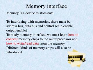
Systems and Technology Group Memory Interface Controller (MIC) 17 © IBM Corporation, 2005, All rights reserved
Systems and Technology Group EIB Memory Interface Controller (MIC) Command and Data Flow EIB Interface Command Sort Two independent 32b controllers 25.6 GB/s @ 3.2 Gb/s 32 read and 32 write queues for each channel All accesses are closed page SEC/DED ECC Speculative read support Remote connection to EIB XIO1 Dataflow XIO0 Dependency Check Dependency Check Dataflow 1.6 Ghz Proc Sync Buffers XIO 0 – Cmd Queues Read Q Buffers Read Write Write Q XIO 0 – Cmd Queues Read Q Read Write Write Q Scrub Init Refresh Scrub Init Refresh Cmd Reorder & Arbitration ECC Correct ECC Cmd Reorder & Arbitration 1.6 Ghz Rambus Sync ECC Correct ECC Generate Generate DRAM Control Mux & Dist DRAM Control Mux & Dist 400 Mhz Rambus XIO 0 XIO 1 18 © IBM Corporation, 2005, All rights reserved
Systems and Technology Group Memory Interface Controller Overview Capacity Dependent on XDRAM size & width Minimum of one 32b interface fully connected 2 x 16b - 256 Mb XDRAMs = 64 MB Maximum of 2 x 32b interface fully connected Theoretical Maximum 64 x 1bit - 8 Gb XDRAMs = 64 GB Clocking The Rambus interface runs at 400 Mhz which is called a Pclk Memory Controller logic runs at ½ the processor frequency = 1.6 GHz with an asynchronous crossing to the Rambus clock domain which also runs at 1.6 GHz (multiplied up Pclk) The MIC dataflow distributes the data to the Rambus interface at 1.6 GHz and widens the datapath in the last level of logic to interface with the Rambus macro The Rambus macro then has an 8:1 clock ratio to drive the data out at 3.2 Gb/s per differential pair 19 © IBM Corporation, 2005, All rights reserved
Systems and Technology Group Memory Interface Controller Overview Logical to Physical Memory Map Interleaves across channels Interleaves across internal banks Enables closed bank memory controller to maximize random access bandwidth Programmable Command Reordering to maximize bandwidth utilization Command selection will tend to group commands into burst of 8 or 16 in a row before switching the bus Bank conflicts, high priority reads, dependencies or lack of available commands can cause bus turnarounds Memory Scrubbing to correct Single Bit Errors (optional) Frequency: Once every 20.6 msec Duration: One read is performed. A write is performed if a single bit error is found and corrected. Refreshes Frequency: Once every .49 usec Duration: 1 command (4 Rambus Pclks) 20 © IBM Corporation, 2005, All rights reserved
Systems and Technology Group Design to Support XDR Dram Controller Power on Initialization & Calibration Timing Calibration, Receive/Transmit, Setup and Hold Current Calibrations for drivers and receivers Impedance Calibrations for drivers and receivers Periodic Calibration Periodic Timing Calibration, Receive/Transmit, Setup and Hold Frequency: Once every 8 msec Duration: 64 Rambus Pclks (4 separate operations) Current and Impedance Calibrations for drivers and receivers Frequency: Once every 8 msec Duration: 64 Rambus Pclks (4 separate operations) Early Read Used to minimize Read to Write turnaround gap on the DRAM data busses Write masking support for 16B to 128B writes Data dependant function Requires Hardware calculation of ECC before storage into the Write data buffer 21 © IBM Corporation, 2005, All rights reserved
Systems and Technology Group Summary High Bandwidth Interconnect Dual XDRTM Memory Controller (25.6 GB/s @ 3.2 Gbps) Two I/O interfaces (60 GB/s @ 5 Gbps) Internal Element Interconnect (peak BW over 300 GB/s @ 3.2 GHz) Resource Allocation Management Flexible and Scalable Multiple System Configurations Configurable I/O Interface Bandwidth Coherent and Non-coherent protocols Configurable Memory Capacity and Bandwidth Internal Modular Interconnect Bus Memory and I/O Interfaces Asynchronous to Processor Core 22 © IBM Corporation, 2005, All rights reserved