Download
1 / 92
1.01k likes | 1.76k Vues
Explore bus arrangements, components, and protection techniques for efficient power system operation and fault mitigation. Learn about CT saturation issues, application considerations, and advanced bus protection schemes to enhance system reliability.

E N D
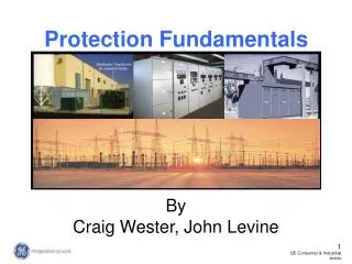
Fundamentals ofBus Bar Protection GE Multilin
Outline • Bus arrangements • Bus components • Bus protection techniques • CT Saturation • Application Considerations: • High impedance bus differential relaying • Low impedance bus differential relaying • Special topics
Single bus - single breaker • Distribution and lower transmission voltage levels • No operating flexibility • Fault on the bus trips all circuit breakers
Multiple bus sections - single breaker with bus tie • Distribution and lower transmission voltage levels • Limited operating flexibility
Double bus - single breaker with bus tie • Transmission and distribution voltage levels • Breaker maintenance without circuit removal • Fault on a bus disconnects only the circuits being connected to that bus
Main and transfer buses • Increased operating flexibility • A bus fault requires tripping all breakers • Transfer bus for breaker maintenance
Double bus – single breaker w/ transfer bus • Very high operating flexibility • Transfer bus for breaker maintenance
Double bus - double breaker • High operating flexibility • Line protection covers bus section between two CTs • Fault on a bus does not disturb the power to circuits
Breaker-and-a-half bus • Used on higher voltage levels • More operating flexibility • Requires more breakers • Middle bus sections covered by line or other equipment protection
Ring bus • Higher voltage levels • High operating flexibility with minimum breakers • Separate bus protection not required at line positions
SF6, EHV & HV - Synchropuff Low Voltage circuit breakers Bus components breakers
Oil insulated current transformer (35kV up to 800kV) Gas (SF6) insulated current transformer Bushing type (medium voltage switchgear) CurrentTransformers
Protection Requirements • High bus fault currents due to large number of circuits connected: • CT saturation often becomes a problem as CTs may not be sufficiently rated for worst fault condition case • large dynamic forces associated with bus faults require fast clearing times in order to reduce equipment damage • False trip by bus protection may create serious problems: • service interruption to a large number of circuits (distribution and sub-transmission voltage levels) • system-wide stability problems (transmission voltage levels) • With both dependability and security important, preference is always given to security
Bus Protection Techniques • Interlocking schemes • Overcurrent (“unrestrained” or “unbiased”) differential • Overcurrent percent (“restrained” or “biased”) differential • Linear couplers • High-impedance bus differential schemes • Low-impedance bus differential schemes
Blocking scheme typically used Short coordination time required Care must be taken with possible saturation of feeder CTs Blocking signal could be sent over communications ports (peer-to-peer) This technique is limited to simple one-incomer distribution buses Interlocking Schemes
Differential signal formed by summation of all currents feeding the bus CT ratio matching may be required On external faults, saturated CTs yield spurious differential current Time delay used to cope with CT saturation Instantaneous differential OC function useful on integrated microprocessor-based relays Overcurrent (unrestrained) Differential
0 V 40 V 10 V 10 V 0 V 20 V If = 8000 A 2000 A 2000 A 0 A 4000 A Linear Couplers ZC = 2 – 20 - typical coil impedance (5V per 1000Amps => 0.005 @ 60Hz ) 59 External Fault
If = 8000 A 40 V 0 V 10 V 10 V 0 V 20 V 0 A 2000 A 2000 A 0 A 4000 A Linear Couplers Esec= Iprim*Xm - secondary voltage on relay terminals IR= Iprim*Xm /(ZR+ZC) – minimum operating current where, Iprim – primary current in each circuit Xm – liner coupler mutual reactance (5V per 1000Amps => 0.005 @ 60Hz ) ZR – relay tap impedance ZC – sum of all linear coupler self impedances Internal Bus Fault 59
Fast, secure and proven Require dedicated air gap CTs, which may not be used for any other protection Cannot be easily applied to reconfigurable buses The scheme uses a simple voltage detector – it does not provide benefits of a microprocessor-based relay (e.g. oscillography, breaker failure protection, other functions) Linear Couplers
High Impedance Differential • Operating signal created by connecting all CT secondaries in parallel • CTs must all have the same ratio • Must have dedicated CTs • Overvoltage element operates on voltage developed across resistor connected in secondary circuit • Requires varistors or AC shorting relays to limit energy during faults • Accuracy dependent on secondary circuit resistance • Usually requires larger CT cables to reduce errors higher cost • Cannot easily be applied to reconfigurable buses and offers no advanced functionality
Percent characteristic used to cope with CT saturation and other errors Restraining signal can be formed in a number of ways No dedicated CTs needed Used for protection of re-configurable buses possible Percent Differential
Low Impedance Percent Differential • Individual currents sampled by protection and summated digitally • CT ratio matching done internally (no auxiliary CTs) • Dedicated CTs not necessary • Additional algorithms improve security of percent differential characteristic during CT saturation • Dynamic bus replica allows application to reconfigurable buses • Done digitally with logic to add/remove current inputs from differential computation • Switching of CT secondary circuits not required • Low secondary burdens • Additional functionality available • Digital oscillography and monitoring of each circuit connected to bus zone • Time-stamped event recording • Breaker failure protection
Digital Differential Algorithm Goals • Improve the main differential algorithm operation • Better filtering • Faster response • Better restraint techniques • Switching transient blocking • Provide dynamic bus replica for reconfigurable bus bars • Dependably detect CT saturation in a fast and reliable manner, especially for external faults • Implement additional security to the main differential algorithm to prevent incorrect operation • External faults with CT saturation • CT secondary circuit trouble (e.g. short circuits)
Low Impedance Differential (Distributed) • Data Acquisition Units (DAUs) installed in bays • Central Processing Unit (CPU) processes all data from DAUs • Communications between DAUs and CPU over fiber using proprietary protocol • Sampling synchronisation between DAUs is required • Perceived less reliable (more hardware needed) • Difficult to apply in retrofit applications
Low Impedance Differential (Centralized) • All currents applied to a single central processor • No communications, external sampling synchronisation necessary • Perceived more reliable (less hardware needed) • Well suited to both new and retrofit applications.
CT Saturation Concepts • CT saturation depends on a number of factors • Physical CT characteristics (size, rating, winding resistance, saturation voltage) • Connected CT secondary burden (wires + relays) • Primary current magnitude, DC offset (system X/R) • Residual flux in CT core • Actual CT secondary currents may not behave in the same manner as the ratio (scaled primary) current during faults • End result is spurious differential current appearing in the summation of the secondary currents which may cause differential elements to operate if additional security is not applied
CT Saturation No DC Offset • Waveform remains fairly symmetrical With DC Offset • Waveform starts off being asymmetrical, then symmetrical in steady state
External Fault & Ideal CTs • Fault starts at t0 • Steady-state fault conditions occur at t1 t1 t0 • Ideal CTs have no saturation or mismatch errors thus produce no differential current
External Fault & Actual CTs • Fault starts at t0 • Steady-state fault conditions occur at t1 t1 t0 Actual CTs do introduce errors, producing some differential current (without CT saturation)
External Fault with CT Saturation t2 • Fault starts at t0, CT begins to saturate at t1 • CT fully saturated at t2 t1 t0 • CT saturation causes increasing differential current that may enter the differential element operate region.
Some Methods of Securing Bus Differential • Block the bus differential for a period of time (intentional delay) • Increases security as bus zone will not trip when CT saturation is present • Prevents high-speed clearance for internal faults with CT saturation or evolving faults • Change settings of the percent differential characteristic (usually Slope 2) • Improves security of differential element by increasing the amount of spurious differential current needed to incorrectly trip • Difficult to explicitly develop settings (Is 60% slope enough? Should it be 75%?) • Apply directional (phase comparison) supervision • Improves security by requiring all currents flow into the bus zone before asserting the differential element • Easy to implement and test • Stable even under severe CT saturation during external faults
High Impedance Voltage-operated RelayExternal Fault • 59 element set above max possible voltage developed across relay during external fault causing worst case CT saturation • For internal faults, extremely high voltages (well above 59 element pickup) will develop across relay
High Impedance Voltage Operated Relay Ratio matching with Multi-ratio CTs • Application of high impedance differential relays with CTs of different ratios but ratio matching taps is possible, but could lead to voltage magnification. • Voltage developed across full winding of tapped CT does not exceed CT rating, terminal blocks, etc.
High Impedance Voltage Operated Relay Ratio matching with Multi-ratio CTs • Use of auxiliary CTs to obtain correct ratio matching is also possible, but these CTs must be able to deliver enough voltage necessary to produce relay operation for internal faults.
Electromechanical High Impedance Bus Differential Relays • Single phase relays • High-speed • High impedance voltage sensing • High seismic IOC unit
P -based High-Impedance Bus Differential Protection Relays Operating time: 20 – 30ms @ I > 1.5xPKP
High Impedance Module for Digital Relays RST = 2000 - stabilizing resistor to limit the current through the relay, and force it to the lower impedance CT windings. MOV – Metal Oxide Varistor to limit the voltage to 1900 Volts 86 – latching contact preventing the resistors from overheating after the fault is detected
Fast, secure and proven Requires dedicated CTs, preferably with the same CT ratio and using full tap Can be applied to small buses Depending on bus internal and external fault currents, high impedance bus diff may not provide adequate settings for both sensitivity and security Cannot be easily applied to reconfigurable buses Require voltage limiting varistor capable of absorbing significant energy May require auxiliary CTs Do not provide full benefits of microprocessor-based relay system (e.g. metering, monitoring, oscillography, etc.) High Impedance Bus Protection - Summary
P-based Low-Impedance Relays • No need for dedicated CTs • Internal CT ratio mismatch compensation • Advanced algorithms supplement percent differential protection function making the relay very secure • Dynamic bus replica (bus image) principle is used in protection of reconfigurable bus bars, eliminating the need for switching physically secondary current circuits • Integrated Breaker Failure (BF) function can provide optimal tripping strategy depending on the actual configuration of a bus bar
Small Bus Applications 2-8 Circuit Applications • Up to 24 Current Inputs • 4 Zones • Zone 1 = Phase A • Zone 2 = Phase B • Zone 3 = Phase C • Zone 4 = Not used • Different CT Ratio Capability for Each Circuit • Largest CT Primary is Base in Relay
CB 11 CB 12 Medium to Large Bus Applications 9-12 Circuit Applications • Relay 1 - 24 Current Inputs • 4 Zones • Zone 1 = Phase A (12 currents) • Zone 2 = Phase B (12 currents) • Zone 3 = Not used • Zone 4 = Not used • Relay 2 - 24 Current Inputs • 4 Zones • Zone 1 = Not used • Zone 2 = Not used • Zone 3 = Phase C (12 currents) • Zone 4 = Not used • Different CT Ratio Capability for Each Circuit • Largest CT Primary is Base in Relay
Large Bus Applications 87B phase A 87B phase B 87B phase C Logic relay (switch status, optional BF)
Summing External CurrentsNot Recommended for Low-Z 87B relays • Relay becomes combination of restrained and unrestrained elements • In order to parallel CTs: • CT performance must be closely matched • Any errors will appear as differential currents • Associated feeders must be radial • No backfeeds possible • Pickup setting must be raised to accommodate any errors
Definitions of Restraint Signals “sum of” “scaled sum of” “geometrical average” “maximum of”