Download
1 / 28
310 likes | 668 Vues
Database Systems Design Part III : Mapping ER Diagram to Relational Schema. Software School of Hunan University 2006.09. Database Design Flow Diagram. Intelligence. Individual Part 1. Identify Summary Abstract Deduce, Refine. ER-diagram. Individual Part n. Transformation.

E N D
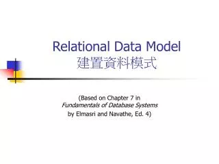
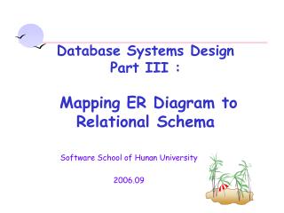
Database Systems Design Part III :MappingER Diagram to Relational Schema Software School of Hunan University 2006.09
Database Design Flow Diagram Intelligence Individual Part 1 Identify Summary Abstract Deduce, Refine ER-diagram Individual Part n Transformation User view 1 Relations Rational Relations User view n Normalization
ER Model to Relational Schemas • The chapter discuss how to convert an ER diagram (or EER diagram) into a corresponding relational schema. • Conceptual database design produces a conceptual ER model. This conceptual model is then converted into the relational model (which is a logical model). • Note that although it is possible to design using the relational model directly, it is normally more beneficial to perform conceptual design using the ER model first.
ER Model to Relational Schemas(2) • Converting an ER model to a relational database schema involves 7 steps. • In general, these steps convert entities to relations and ER relationships to relations. • For 1:1 and 1:N relationships, foreign keys can be used instead of separate relations. • Handling subclasses and superclasses in the EER model requires an extra conversion step. • After conversion is performed, normalization and optimization are often performed to improve the relational schema.
ER Model Example Supervises 0..1 bonus Supervisor Manage 0..* Depart ment Employee 0..1 0..1 Supervisee dno {PK} name eno {PK} name address city street postCode title salary Has 0..* 0..1 0..1 Has 0..* WorkOn Project Has 1..1 0..* 0..* pno {PK} name budget location[1..3] /totalEmp 0..* Dependent responsibility duration name age
ER to Relational MappingStep #1: Convert Strong Entities • Step #1: Convert each strong entity to a relation. • Notes: 1) Attributes of the entity type become attributes of the relation. 2) Include only simple attributes in relation. For composite attributes, only create attributes in the relation for their simple components. 3) Multi-valued attributes are handled separately (in step #6). 4) The primary key of the relation is the key attributes for the entity. Employee eno {PK} name address city street postCode title salary Employee (eno, ename , city, street, postcode, title, salary)
ER to Relational Mapping Current Relational Schema - Step #1 • Employee (eno, ename, city, street, postcode, title, salary) • Department (dno, dname) • Project (pno, pname, budget).
ER to Relational MappingStep #2: Convert Weak Entities • Step #2: Convert each weak entity into a relation with foreign keys to its identifying relations (entities). • For each weak entity W with identifying owners E1, E2, …, En create a relation R: • Identify relations R1, R2, …, Rn for entity types E1, E2, …, En. • The primary key of R consists of the primary keys of R1, R2, …, Rn plus the partial key of the weak entity. • Create a foreign key in R to the primary key of each relation R1, R2, …, Rn. • Attributes are converted the same as strong entities.
ER to Relational MappingStep #2: Convert Weak Entities Employee eno (PK) name address city street postCode title salary Employee (eno, ename, city, street, postcode, title, salary) 1..1 Has 0..* Dependent Dependent (eno, name, age) name age
ER to Relational Mapping Current Relational Schema - Step #2 • Dependent (eno, name, age) • Employee (eno, ename, city, street, postcode, title, salary) • Department (dno, dname) • Project (pno, pname, budget).
ER to Relational MappingSteps #3-5: Convert Relationships Steps 3 to 5 convert binary relationships of cardinality: • 1:1 - Step #3 • 1:N - Step #4 • M:N - Step #5 Note that M:N relationships are the most general case. • In general, each ER relationship can be mapped to a relation. • However, for 1:1 and 1:N relationships, it is more efficient to combine the relationship with an existing relation instead of creating a new one. Relationships that are not binary are handled in step #7.
ER to Relational MappingStep #3: Convert 1:1 Relationships Step #3: Convert binary 1:1 relationships into a UNIQUE foreign key reference from one relation to the other. Given a binary 1:1 relationship R between two entities Ei and Ej: • Identify the corresponding relations Ri and Rj. • Chose one of the relations, say Ri, and: • Add the attributes of R to Ri. • Add the primary key attributes of Rj to Ri, and create a foreign key reference to Rj from Ri. • Declare these primary key attributes of Rj to be UNIQUE. • Notes: You can select either Ri or Rj. Typically, it is best to select the relation that is guaranteed to always participate in the relationship or the one that will participate the most in the relationship.
ER to Relational MappingStep #3: Convert 1:1 Relationships (2) Employee Manage Depart ment 0..1 0..1 eno (PK) name address city street postCode title salary dno (PK) name bonus Department (dno, dname) Manages (eno, dno, bonus) Employee (eno, ename, city, street, postcode, title, salary) Department (dno, dname, mgreno, bonus) Note: Renamed eno to mgreno for clarity.
ER to Relational MappingStep #4: Convert 1:N Relationships Step #4: Convert binary 1:N relationships between into a foreign key reference from the N-side relation to the 1-side relation. Given a binary 1:N relationship R between two entities Ei and Ej: Identify the corresponding relations Ri and Rj. Let Ri be the N-side of the relation. • Add the attributes of R to Ri. • Add the primary key attributes of Rj to Ri, and create a foreign key reference to Rj from Ri. Notes: Unlike 1:1 relationships, you must select the N-side of the relationship as the relation containing the foreign key and relationship attributes.
ER to Relational MappingStep #4: Convert 1:N Relationships Has Depart ment Employee 0..* 0..1 dno {PK} name eno {PK} name address city street postCode title salary InDept (dno, eno) Department (dno, dname) Employee (eno, ename, city, street, postcode, title, salary) Employee (eno, ename, city, street, postcode, title, salary,dno)
ER to Relational MappingStep #4: Convert 1:N Relationships Has Depart ment Project 0..* 0..1 dno {PK} name pno {PK} name budget location[1..3] /totalEmp DeptProj (dno, pno) Department (dno, dname) Project (pno, pname, budget) Project (pno, pname, budget, dno)
ER to Relational MappingStep #4: Convert 1:N Relationships Supervises Supervises (supereno, eno) 0..1 Supervisor 0..* Employee eno {PK} name address city street postCode title salary Employee (eno, ename, city, street, postcode, title, salary,dno) Employee (eno, ename, city, street, postcode, title, salary,dno, supereno)
ER to Relational MappingCurrent Relational Schema - Step #4 Dependent (eno, name, age) Employee (eno, ename, city, street, postcode, title, salary,dno, supereno) Department (dno, dname, mgreno, bonus) Project (pno, pname, budget, dno)
ER to Relational MappingStep #5: Convert M:N Relationships Step #5: Convert binary M:N relationships into a new relation with foreign keys to the two participating entities. Given a binary M:N relationship between entities Ei and Ej: Identify the corresponding relations Ri and Rj. • Create a new relation R representing the relationship where: • R contains the relationship attributes. • The primary key of R is a composite key consisting of the primary keys of Ri and Rj. • Add the primary key attributes of Ri and Rj to R, and create a foreign key reference to Ri from R and to Rj from R.
ER to Relational MappingStep #5: Convert M:N Relationships WorkOn Project Employee 0..* 0..* pno {PK} name budget location[1..3] eno {PK} name address city street postCode title salary responsibility duration Project (pno, pname, budget, dno) WorksOn (eno, pno, responsibility, duration) Employee (eno, ename, city, street, postcode, title, salary, dno, supereno)
ER to Relational MappingCurrent Relational Schema - Step #5 Dependent (eno, name, age) Employee (eno, ename, state, city, street, title, salary,dno, supereno) Department (dno, dname, mgreno, bonus) Project (pno, pname, budget, dno) WorksOn (eno, pno, Responsibility, Duration)
ER to Relational MappingStep 6: Convert Multi-Valued Attributes Step #6: Convert a multi-valued attribute into a relation with composite primary key consisting of the attribute value plus the primary key of the attribute's entity. Given a multi-valued attribute A of entity Ei: Identify the corresponding relation Ri. Create a new relation R representing the attribute where: • R contains the simple, single-valued attribute A. • Add the primary key attributes of Ri to R, and create a foreign key reference to Ri from R. • The primary key of R is a composite key consisting of the primary key of Ri and A.
ER to Relational MappingConvert Multi-Valued Attributes - Step #6 Project pno {PK} name budget location[1..3] Project (pno, name, budget, dno) ProjectLocation (pno, location)
ER to Relational MappingFinal Relational Schema Dependent (eno, name, age) Employee (eno, ename, state, city, street, title, salary,dno, supereno) Department (dno, dname, mgreno, bonus) Project (pno, pname, budget, dno) ProjectLocation (pno, location) WorksOn (eno, pno, Responsibility, Duration)
ER to Relational Mapping Step #7: Convert n-ary Relationships Step #7: Convert n-ary relationships by creating a new relation to represent the relationship and creating foreign keys that reference the related entities. Given an n-ary relationship between entities E1, E2, …, En: Identify relations R1, R2, …., Rn for entity types E1, E2, …, En. Create a new relation R to represent the relationship. • The primary key of R consists of the primary keys of R1, R2, …., Rn. • Create a foreign key in R to the primary key of each relation R1, R2, …, Rn. • Attributes of the relationship become attributes of R.
ER to Relational Mapping Step #7: Convert n-ary Relationships quantity price Provide Project Component 0..* 0..* pno {PK} name budget cno {PK} name desciption 0..* Supplier sno {PK} name address Provide (pno, sno, cno, quantity, price)
Summary of ER to Relational Mapping ER Model Relational Model Entity Type Relation 1:1 or 1:N Relationship Type Foreign key (or "relationship" relation) M:N Relationship Type "Relationship" relation and 2 foreign keys n-ary Relationship Type "Relationship" relation and n foreign keys Simple attribute Attribute Composite attribute Set of simple component attributes Multi-valued attribute Relation and foreign key Key attribute Primary (or unique) key
amount price Part Order InOrder 0..* 0..* pno {PK} name price number {PK} date /totalAmont 0..* Supplier 0..* sid {PK} name 0..* 0..* Places Supplies 0..* In 1..1 1..1 Customer In Nation cseqnum {PK} name 0..* 1..1 name {PK} Exercises