Graphs
Graphs. Chapter 10. Chapter Summary. Graphs and Graph Models Graph Terminology and Special Types of Graphs Representing Graphs and Graph Isomorphism Connectivity Euler and Hamiltonian Paths. Graphs and Graph Models. Section 10.1. Section Summary. Introduction to Graphs Graph Taxonomy


Graphs
E N D
Presentation Transcript
Graphs Chapter 10
Chapter Summary • Graphs and Graph Models • Graph Terminology and Special Types of Graphs • Representing Graphs and Graph Isomorphism • Connectivity • Euler and Hamiltonian Paths
Graphs and Graph Models Section 10.1
Section Summary • Introduction to Graphs • Graph Taxonomy • Graph Models
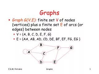
Graphs Definition: A graphG = (V, E)consists of a nonempty set V of vertices (or nodes) and a set E of edges. Each edge has either one or two vertices associated with it, called its endpoints. An edge is said to connect its endpoints. Remarks: • We have a lot of freedom when we draw a picture of a graph. All that matters is the connections made by the edges, not the particular geometry depicted. For example, the lengths of edges, whether edges cross, how vertices are depicted, and so on, do not matter • A graph with an infinite vertex set is called an infinite graph. A graph with a finite vertex set is called a finite graph. We restrict our attention to finite graphs. Example: This is a graph with four vertices and five edges. a b d c
Some Terminology • In a simple graph each edge connects two different vertices and no two edges connect the same pair of vertices. • Multigraphs may have multiple edges connecting the same two vertices. When m different edges connect the vertices u and v, we say that {u,v}is an edge of multiplicitym. • An edge that connects a vertex to itself is called a loop. • A pseudograph may include loops, as well as multiple edges connecting the same pair of vertices. a b Example: This pseudograph has both multiple edges and loops. Remark: There is no standard terminology for graph theory. So, it is crucial that you understand the terminology being used whenever you read material about graphs. c
Directed Graphs Definition: An directed graph (or digraph) G = (V, E)consists of a nonempty set V of vertices (or nodes) and a set E of directed edges (or arcs). Each edge is associated with an ordered pair of vertices. The directed edge associated with the ordered pair (u,v) is said to start at u and end atv. Remark: • Graphs where the end points of an edge are not ordered are said to be undirected graphs.
Some Terminology (continued) • Asimple directed graph has no loops and no multiple edges. • Adirected multigraph may have multiple directed edges. When there are m directed edges from the vertex u to the vertex v, we say that (u,v)is an edge of multiplicity m. b a b a Example: This is a directed graph with three vertices and four edges. c c Example: In this directed multigraph the multiplicity of (a,b) is 1 and the multiplicity of (b,c) is 2.
Graph Models: Computer Networks • When we build a graph model, we use the appropriate type of graph to capture the important features of the application. • We illustrate this process using graph models of different types of computer networks. In all these graph models, the vertices represent data centers and the edges represent communication links. • To model a computer network where we are only concerned whether two data centers are connected by a communications link, we use a simple graph. This is the appropriate type of graph when we only care whether two data centers are directly linked (and not how many links there may be) and all communications links work in both directions.
Graph Models: Computer Networks (continued) • To model a computer network where we care about the number of links between data centers, we use a multigraph. • To model a computer network with diagnostic links at data centers, we use a pseudograph, as loops are needed. • To model a network with multiple one-way links, we use a directed multigraph. Note that we could use a directed graph without multiple edges if we only care whether there is at least one link from • a data center to another data center.
Graph Terminology: Summary • To understand the structure of a graph and to build a graph model, we ask these questions: • Are the edges of the graph undirected or directed (or both)? • If the edges are undirected, are multiple edges present that connect the same pair of vertices? If the edges are directed, are multiple directed edges present? • Are loops present?
Other Applications of Graphs • We will illustrate how graph theory can be used in models of: • Social networks • Communications networks • Information networks • Software design • Transportation networks • Biological networks • It’s a challenge to find a subject to which graph theory has not yet been applied. Can you find an area without applications of graph theory?
Graph Models: Social Networks • Graphs can be used to model social structures based on different kinds of relationships between people or groups. • In a social network, vertices represent individuals or organizations and edges represent relationships between them. • Useful graph models of social networks include: • friendship graphs -undirected graphs where two people are connected if they are friends (in the real world, on Facebook, or in a particular virtual world, and so on.) • collaboration graphs -undirected graphs where two people are connected if they collaborate in aspecific way • influence graphs-directed graphs where there is an edge from one person to another if the first person can influence the second person
Graph Models: Social Networks (continued) Example: A friendship graph where two people are connected if they are Facebook friends. Example: An influence graph
Examples of Collaboration Graphs • The Hollywood graph models the collaboration of actors in films. • We represent actors by vertices and we connect two vertices if the actors they represent have appeared in the same movie. • An academic collaboration graph models the collaboration of researchers who have jointly written a paper in a particular subject. • We represent researchers in a particular academic discipline using vertices. • We connect the vertices representing two researchers in this discipline if they are coauthors of a paper. • We will study the academic collaboration graph for mathematicians when we discuss Erdős numbers in Section 10.4.
Applications to Information Networks • Graphs can be used to model different types of networks that link different types of information. • In a web graph, web pages are represented by vertices andlinks are represented by directed edges. • A web graph models the web at a particular time. • The web graph is used by search engines • In a citation network: • Research papers in a particular discipline are represented by vertices. • When a paper cites a second paper as a reference, there is an edge from the vertex representing this paper to the vertex representing the second paper.
Transportation Graphs • Graph models are extensively used in the study of transportation networks. • Airline networks can be modeled using directed multigraphs where • airports are represented by vertices • each flight is represented by a directed edge from the vertex representing the departure airport to the vertex representing the destination airport • Road networks can be modeled using graphs where • vertices represent intersections and edges represent roads. • undirected edges represent two-way roads and directed edges represent one-way roads.
Software Design Applications • Graph models are extensively used in software design. We will introduce two such models here; one representing the dependency between the modules of a software application and the other representing restrictions in the execution of statements in computer programs. • When a top-down approach is used to design software, the system is divided into modules, each performing a specific task. • We use a module dependency graph to represent the dependency between these modules. These dependencies need to be understood before coding can be done. • In a module dependency graph vertices represent software modules and there is an edge from one module to another if the second module depends on the first. Example: The dependencies between the seven modules in the design of a web browser are represented by this module dependency graph.
Software Design Applications (continued) • We can use a directed graph called a precedence graph to represent which statements must have already been executed before we execute each statement. • Vertices represent statements in a computer program • There is a directed edge from a vertex to a second vertex if the second vertex cannot be executed before the first Example: This precedence graph shows which statements must already have been executed before we can execute each of the six statements in the program.
Biological Applications • Graph models are used extensively in many areas of the biological science. We will describe two such models, one to ecology and the other to molecular biology. • Niche overlap graphs model competition between species in an ecosystem • Vertices represent species and an edge connects two vertices when they represent species who compete for food resources. Example: This is the niche overlap graph for a forest ecosystem with nine species.
Biological Applications (continued) • We can model the interaction of proteins in a cell using a protein interaction network. • In a protein interaction graph, vertices represent proteins and vertices are connected by an edge if the proteins they represent interact. • Protein interaction graphs can be huge and can contain more than 100,000 vertices, each representing a different protein, and more than 1,000,000 edges, each representing an interaction between proteins • Protein interaction graphs are often split into smaller graphs, called modules, which represent the interactions between proteins involved in a particular function. Example: This is a module of the protein interaction graph of proteins that degrade RNA in human cells.
Graph Terminology and Special Types of Graphs Section 10.2
Section Summary • Basic Terminology • Some Special Types of Graphs • Bipartite Graphs • New Graphs from Old
Basic Terminology Definition 1. Two vertices u, v in an undirected graph G are called adjacent (or neighbors) in G if there is an edge e between u and v. Such an edge e is called incident with the vertices u and v and e is said to connect u and v. Definition 2. The set of all neighbors of a vertex v of G = (V, E), denoted by N(v), is called the neighborhoodof v. If A is a subset of V, we denote by N(A) the set of all vertices in G that are adjacent to at least one vertex in A. So, Definition 3. The degree of a vertex in a undirected graph is the number of edges incident with it, except that a loop at a vertex contributes two to the degree of that vertex. The degree of the vertex v is denoted by deg(v).
Degrees and Neighborhoods of Vertices Example: What are the degrees and neighborhoods of the vertices in the graphs G and H? Solution: G: deg(a) = 2, deg(b) = deg(c) = deg(f ) = 4, deg(d ) = 1, deg(e) = 3,deg(g) = 0. N(a) = {b, f }, N(b) = {a, c, e, f }, N(c) = {b, d, e, f }, N(d) = {c}, N(e) = {b, c , f }, N(f) = {a, b, c, e},N(g) = . H: deg(a) = 4, deg(b) = deg(e) = 6, deg(c) = 1,deg(d) = 5. N(a) = {b, d, e}, N(b) = {a, b, c, d, e},N(c) = {b}, N(d) = {a, b, e}, N(e) = {a, b ,d}.
Degrees of Vertices Theorem 1 (Handshaking Theorem): If G= (V,E) is an undirected graph with medges, then Proof: Each edge contributes twice to the degree count of all vertices. Hence, both the left-hand and right-hand sides of this equation equal twice the number of edges. Think about the graph where vertices represent the people at a party and an edge connects two people who have shaken hands.
Handshaking Theorem We now give two examples illustrating the usefulness of the handshaking theorem. Example: How many edges are there in a graph with 10 vertices of degree six? Solution: Because the sum of the degrees of the vertices is 6 10 = 60, the handshaking theorem tells us that 2m = 60. So the number of edges m = 30. Example: If a graph has 5 vertices, can each vertex have degree 3? Solution: This is not possible by the handshaking thorem, because the sum of the degrees of the vertices 3 5 = 15 is odd.
Degree of Vertices (continued) Theorem 2: An undirected graph has an even number of vertices of odd degree. Proof: Let V1 be the vertices of even degree and V2 be the vertices of odd degree in an undirected graph G = (V, E) with m edges. Then even This sum must be even because 2m is even and the sum of the degrees of the vertices of even degrees is also even. Because this is the sum of the degrees of all vertices of odd degree in the graph, there must be an even number of such vertices. must be even since deg(v) is even for each v∈ V1
Directed Graphs Recall the definition of a directed graph. Definition: An directed graph G = (V, E) consists of V, a nonempty set of vertices (or nodes), and E, a set of directed edges or arcs. Each edge is an ordered pair of vertices. The directed edge (u,v) is said to start at u and end at v. Definition: Let (u,v)be an edge in G. Then u is the initial vertex of this edge and is adjacent to v and v is the terminal (or end)vertex of this edge and is adjacent from u. The initial and terminal vertices of a loop are the same.
Directed Graphs (continued) Definition: The in-degree of a vertex v, denoted deg−(v), is the number of edges which terminate at v. The out-degree of v, denoted deg+(v), is the number of edges with v as their initial vertex. Note that a loop at a vertex contributes 1 to both the in-degree and the out-degree of the vertex. Example: In the graph G we have deg−(a) = 2, deg−(b) = 2, deg−(c) = 3, deg−(d) = 2, deg−(e) = 3,deg−(f) = 0. deg+(a) = 4, deg+(b) = 1, deg+(c) = 2, deg+(d) = 2, deg+(e) = 3,deg+(f) = 0.
Directed Graphs (continued) Theorem 3: Let G = (V, E)be a graph with directed edges. Then: Proof: The first sum counts the number of outgoing edges over all vertices and the second sum counts the number of incoming edges over all vertices. It follows that both sums equal the number of edges in the graph.
Special Types of Simple Graphs: Complete Graphs A complete graph on n vertices, denoted by Kn, is the simple graph that contains exactly one edge between each pair of distinct vertices.
Special Types of Simple Graphs: Cycles and Wheels AcycleCnfor n≥ 3 consists of n vertices v1, v2 ,⋯ ,vn, and edges {v1, v2}, {v2, v3},⋯ , {vn-1, vn}, {vn, v1}. A wheelWnis obtained by adding an additional vertex to a cycle Cnfor n ≥ 3 and connecting this new vertex to each of the n vertices in Cn by new edges.
Special Types of Simple Graphs: n-Cubes An n-dimensional hypercube, or n-cube, Qn, is a graph with 2n vertices representing all bit strings of length n, where there is an edge between two vertices that differ in exactly one bit position.
Special Types of Graphs and Computer Network Architecture Various special graphs play an important role in the design of computer networks. • Some local area networks use a star topology, which is a complete bipartite graph K1,n ,as shown in (a). All devices are connected to a central control device. • Other local networks are based on a ring topology, where each device is connected to exactly two others using Cn,as illustrated in (b). Messages may be sent around the ring. • Others, as illustrated in (c), use a Wn – based topology, combining the features of a star topology and a ring topology. • Various special graphs also play a role in parallel processing where processors need to be interconnected as one processor may need the output generated by another. • The n-dimensional hypercube, or n-cube, Qn, is a common way to connect processors in parallel, e.g., Intel Hypercube. • Another common method is the mesh network, illustrated here for 16 processors.
Bipartite Graphs Definition: A simple graph G is bipartite if V can be partitioned into two disjoint subsets V1and V2 such that every edge connects a vertex in V1 and a vertex in V2. In other words, there are no edges which connect two vertices in V1 or in V2. It is not hard to show that an equivalent definition of a bipartite graph is a graph where it is possible to color the vertices red or blue so that no two adjacent vertices are the same color. H is not bipartite since if we color a red, then the adjacent vertices f and b must both be blue. G is bipartite
Bipartite Graphs (continued) Example: Show that C6 is bipartite. Solution: We can partition the vertex set into V1 = {v1, v3, v5} and V2= {v2, v4, v6} so that every edge of C6 connects a vertex in V1 and V2 . Example: Show that C3 is not bipartite. Solution: If we divide the vertex set of C3 into two nonempty sets, one of the two must contain two vertices. But in C3 every vertex is connected to every other vertex. Therefore, the two vertices in the same partition are connected. Hence, C3 is not bipartite.
Complete Bipartite Graphs Definition: A complete bipartite graphKm,n is a graph that has its vertex set partitioned into two subsets V1 of size m and V2 of size n such that there is an edge from every vertex in V1 to every vertex in V2. Example: We display four complete bipartite graphs here.
New Graphs from Old Definition: A subgraphof a graph G = (V,E) is a graph (W,F), where W⊂ V and F ⊂ E. A subgraphH of G is a proper subgraph of G if H≠ G. Example: Here we show K5and one of its subgraphs. Definition: Let G = (V, E) be a simple graph. The subgraph induced by asubset W of the vertex set V is the graph (W,F), where the edge set F contains an edge in E if and only if both endpoints are in W. Example: Here we show K5 and the subgraph induced by W = {a,b,c,e}.
Bipartite Graphs and Matchings • Bipartite graphs are used to model applications that involve matching the elements of one set to elements in another, for example: • Job assignments - vertices represent the jobs and the employees,edges link employees with those jobs they have been trained to do. A common goal is to match jobs to employees so that the most jobs are done. • Marriages on an island - vertices represent the men and the women and edges link a a man and a woman if they are an acceptable spouse. We may wish to find the largest number of possible marriages.
New Graphs from Old (continued) Definition: The union of two simple graphs G1 = (V1, E1)and G2 = (V2, E2)is the simple graph with vertex set V1⋃V2and edge set E1⋃E2. The union ofG1andG2is denoted by G1⋃ G2. Example:
Representing Graphs and Graph Isomorphism Section 10.3
Section Summary • Adjacency Lists • Adjacency Matrices • Incidence Matrices • Isomorphism of Graphs
Representing Graphs: Adjacency Lists Definition: An adjacency list can be used to represent a graph with no multiple edges by specifying the vertices that are adjacent to each vertex of the graph. Example: Example:
Representation of Graphs: Adjacency Matrices Definition: Suppose that G = (V, E) is a simple graph where |V| = n. Arbitrarily list the vertices of G as v1, v2, … , vn. The adjacency matrix AG of G, with respect to the listing of vertices, is the n ×n zero-one matrix with 1 as its (i, j)th entry when viand vj are adjacent, and 0 as its (i, j)th entry when they are not adjacent. • In other words, if the graphs adjacency matrix is AG = [aij], then
Adjacency Matrices (continued) Example: When a graph is sparse, that is, it has few edges relatively to the total number of possible edges, it is much more efficient to represent the graph using an adjacency list than an adjacency matrix. But for a dense graph, which includes a high percentage of possible edges, an adjacency matrix is preferable. The ordering of vertices isa, b, c, d. The ordering of vertices isa, b, c, d. Note: The adjacency matrix of a simple graph is symmetric, i.e., aij= aji Also, since there are no loops, each diagonal entry aij for i = 1, 2, 3, …, n, is 0.
Adjacency Matrices (continued) • Adjacency matrices can also be used to represent graphs with loops and multiple edges. • A loop at the vertex vi is represented by a 1 at the (i, i)th position of the matrix. • When multiple edges connect the same pair of vertices vi and vj, (or if multiple loops are present at the same vertex), the (i, j)th entry equals the number of edges connecting the pair of vertices. Example: We give the adjacency matrix of the pseudograph shown here using the ordering of vertices a, b, c, d.
Adjacency Matrices (continued) • Adjacency matrices can also be used to represent directed graphs. The matrix for a directed graph G = (V, E) has a 1 in its (i, j)th position if there is an edge from vito vj, where v1, v2, … vn is a list of the vertices. • In other words, if the graphs adjacency matrix is AG= [aij], then • The adjacency matrix for a directed graph does not have to be symmetric, because there may not be an edge from vito vj, when there is an edge from vjto vi. • To represent directed multigraphs, the value of aij is the number of edges connecting vito vj.
Representation of Graphs: Incidence Matrices Definition: Let G = (V, E) be an undirected graph with vertices where v1, v2, … vn and edges e1, e2, … em. The incidence matrix with respect to the ordering of V and E is the n ×m matrix M = [mij], where
Incidence Matrices (continued) Example: Simple Graph and Incidence Matrix The rows going from top to bottom represent v1through v5and the columns going from left to right represent e1throughe6. Example: Pseudograph and Incidence Matrix The rows going from top to bottom represent v1throughv5and the columns going from left to right represent e1throughe8.